Introduction to Sequential Logic & Memory Storage Elements: Door Lock Example
Explore memory storage elements including latches and flip-flops in sequential logic systems. Learn through examples like door combination locks to understand state diagrams and how these elements function. Dive into concepts of clocking, input-output behavior, and terminology in memory storage in digital systems.

Introduction to Sequential Logic & Memory Storage Elements: Door Lock Example
E N D
Presentation Transcript
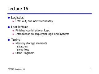
Lecture 16 • Logistics • HW5 out, due next wednesday • Last lecture • Finished combinational logic • Introduction to sequential logic and systems • Today • Memory storage elements • Latches • Flip-flops • State Diagrams 16
Example from last time • Door combination lock • Enter three numbers in sequence and the door opens • When one number is entered, press ‘enter’ • If there is an error the lock must be reset • After the door opens the lock must be reset • Inputs: Sequence of numbers, reset, enter • Outputs: Door open/close • Memory: Must remember the combination • Memory: Must remember which state we are in 16
The “WHY” slide • Memory storage elements • In order to do fun problems like the door combination lock, we must know the building blocks (like how you had to learn AND and OR before you could do functional things). Be patient --- once you know these elements, you can build a lot of meaningful functions • State diagrams • For combinational logic, truth table was an invaluable visualization tool for a function. For sequential logic, state diagram serves as a way to visualize a function. 16
D Q Q CLK The D latch: store it and look it up • Output depends on clock • Clock high: Input passes to output • Clock low: Latch holds its output • Latch are level sensitive and transparent Output Input Output CLK D Qlatch 16
How do we store info like the latch? • Two inverters hold a bit • As long as power is applied • Storing a new memory • Temporarily break the feedback path "1" "0" "stored bit" "remember" "load" "stored bit" "data" 16
D Q Q CLK The D flip-flop • Input sampled at clock edge • Rising edge: Input passes to output • Otherwise: Flip-flop holds its output • Flip-flops are rising-edge triggered or falling-edge triggered Output Input Output CLK D Qff 16
W X Q Clk Q’ Y Z D How do we make a D flip flop? • Edge triggering is difficult • You can do this at home: • Label the internal nodes • Draw a timing diagram • Start with Clk=1 16
Rising-edge triggered D flip-flop Output Input Output D D Q Q Q Q CLK CLK Terminology & notation Positive D latch Output Input D Q Output Q CLK Falling-edge triggered D flip-flop Negative D latch Output Output Input Input D Q Output Output Q CLK 16
D Q Q D Q Q CLK Latches versus flip-flops CLK D Qff Qlatch CLK behavior is the same unless input changes while the clock is high 16
T flip-flop • Full name: Toggle flip-flop • Output toggles when input is asserted • If T=1, then Q Q' when CLK • If T=0, then Q Q when CLK Input(t) Q(t) Q(t + t) Input Q T Q 0 0 0 > 0 1 1 1 0 1 CLK 1 1 0 16
S R Q0 0 hold0 1 01 0 11 1 disallow R Q S Q The SR latch • Cross-coupled NOR gates • Can set (S=1, R=0) or reset (R=1, S=0) the output Reset Set 16
S R Q0 0 hold0 1 01 0 11 1 disallow R Q Q' S NOR output is 1 Only when both inputs are 0 SR latch behavior • Truth table and timing Hold Race Reset Set Reset Set 100 R S Q Q' 16
SR latch is glitch sensitive • Static 0 hazards can set/reset latch • Glitch on S input sets latch • Glitch on R input resets latch R 0 Q S Q' 0 16
The master-slave D Master D latch Slave D latch X Output Input D Q D Q CLK 16
Clear and preset in flip-flops • Clear and Preset set flip-flop to a known state • Used at startup, reset • Clear or Reset to a logic 0 • Synchronous: Q=0 when next clock edge arrives • Asynchronous: Q=0 when reset is asserted • Doesn't wait for clock • Quick but dangerous • Preset or Set the state to logic 1 • Synchronous: Q=1 when next clock edge arrives • Asynchronous: Q=1 when reset is asserted • Doesn't wait for clock • Quick but dangerous 16
State diagrams • How do we characterize logic circuits? • Combinational circuits: Truth tables • Sequential circuits: State diagrams • First draw the states • States Unique circuit configurations • Second draw the transitions between states • Transitions Changes in state caused by inputs 16
S R Q0 0 hold0 1 01 0 11 1 disallow R Q Q' S Example: SR latch • Begin by drawing the states • States Unique circuit configurations • Possible values for feedback (Q, Q') SR=10 SR=00 SR=01 SR=00 SR=10 Q Q'0 1 SR=01 Q Q'1 0 SR=01 SR=10 SR=11 Q Q'0 0 SR=11 SR=11 SR=00 SR=11 SR=00 SR=01 SR=10 Q Q'1 1 possible oscillationbetween states 00 and 11 16
R Q Q' S SR=10 SR=00 SR=01 SR=00 SR=10 Q Q'0 1 Q Q'1 0 SR=01 Observed SR latch behavior • The 1–1 state is transitory • Either R or S “gets ahead” • Latch settles to 0–1 or 1–0 state ambiguously • Race condition non-deterministic transition • Disallow (R,S) = (1,1) 16