Download

1 / 9
90 likes | 111 Vues
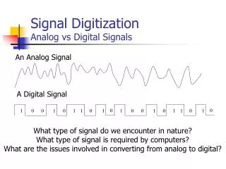
9- dealing with analog signals. Analog Comparator. Positive input chooses bet. PB2 and Bandgap Reference. Negative input chooses bet. PB3 and the 8 inputs of the A/D . ACME= Analog Comparator Mux Enable (Bit 3 in Special Function I/O Reg.).

E N D
Analog Comparator • Positive input chooses bet. PB2 and Bandgap Reference. • Negative input chooses bet. PB3 and the 8 inputs of the A/D. • ACME= Analog Comparator Mux Enable (Bit 3 in Special Function I/O Reg.)
Analog-to-Digital Converter • 10-bit successive approximation • 0.5 LSB Integral Non-linearity • ± 2 LSB Absolute Accuracy • 65 - 260 μs Conversion Time • Up to 15 kSPS at Maximum Resolution • 8 Multiplexed Single Ended Input Channels (PA0 -> PA7) • 7 Differential Input Channels (between any input and PA0/PA1/PA2) • Optional Left Adjustment for ADC Result Readout • 0 - VCC ADC Input Voltage Range • Separate supply voltage pin, AVCC Pin 30 (should be VCC ±0.3 V) • Selectable 2.56V internal Reference Voltage, AVCC, or external reference (Pin 32) • Free Running or Single Conversion Mode • Interrupt on ADC Conversion Complete • Sleep Mode Noise Canceller
Auto Triggering is enabled by setting the ADC Auto Trigger Enable bit. This provides a method of starting conversions at fixed intervals. Using the ADC Interrupt Flag as a trigger source makes the ADC start a new conversion as soon as the ongoing conversion has finished. The ADC then operates in Free Running mode. • The channel and reference selection is continuously updated until a conversion is started. In Free Running mode, always select the channel before starting the first conversion or wait for the first conversion to complete, and then change the channel selection. Since the next conversion has already started automatically, the next result will reflect the previous channel selection. Subsequent conversions will reflect the new channel selection.
ADC Noise Canceler (ADC Noise Reduction mode/ Idle mode) enables conversion during sleep mode to reduce noise induced from the CPU core and other I/O peripherals. • Output = Vin .1024 / VREF • Single ended channels: Input: Mux=111101.22V Mux=11111Gnd
Registers associated with A/D: ADC Multiplexer SelectionRegister ADLAR Bit 5 = 0 : right adjust the result = 1 : Left adjust the result If the result is left adjusted and if no more than 8-bit precision is required, it is sufficient to read ADCH A/D DATA REGISTERS • MUX 3-4 are used by differential input signals (The differential input channels are not tested for devices in PDIP Package). In this case different values of Gain can be selected (1,10,200)
ADC Control and Status Register A • ADEN Bit 7=1: A/D Enable; =0: turn A/D off even during conversion • ADSC Bit 6=1: A/D Start Conversion • ADATE Bit 5=1: Auto Triggering of the ADC is enabled. The ADC will start a conversion on a positive edge of the selected trigger signal. The trigger source is selected by setting the ADC Trigger Select bits, ADTS in SFIOR • ADIF Bit 4: A/D Interrupt Flag is set when an A/D conversion completes. By disabled int this bit is cleared by writing a ‘1’. • ADIE Bit 3=1: A/D Interrupt Enable • Prescalaing: • APDS2-APDS0 Prescalar • 0-7 2-2-4-8-16-32-64-128 (the successive approximation circuitry requires a clock frequency between 50 kHz and 200 kHz to get maximum resolution)
Special Function I/O Register: ADTS2-0: ADC Auto Trigger Source Selections: (ADC INT flag)