Download
1 / 27
370 likes | 857 Vues
Bolted joint failure modes. F. Matthews, in Handbook of Polymer Composites for Engineers. Lay-up 1: [+45,0,-45,0,90,0,+45,0,-45,0] s Lay-up 2: [+45,-45,0 2 ,+45,90,-45,0 3 ] s Lay-up 3: [+45,-45,+45,-45,90,0 5 ] s Lay-up 4: [+45,-45,0 2 ,90,0,+45,-45,0 2 ] s Lay-up 5:

E N D
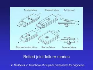
Bolted joint failure modes F. Matthews, in Handbook of Polymer Composites for Engineers
Lay-up 1: [+45,0,-45,0,90,0,+45,0,-45,0]s Lay-up 2: [+45,-45,02,+45,90,-45,03]s Lay-up 3: [+45,-45,+45,-45,90,05]s Lay-up 4: [+45,-45,02,90,0,+45,-45,02]s Lay-up 5: [+45,-45,05,+45,-45,90]s Effect of ‘blocked’ laminate stacking sequence on bearing strength
Simplified procedures for designing composite bolted joints from CC Chamis, J Reinf Plast & Comp.,vol 9, pp614-626
e w d laminate thickness = t Basic bolt geometry F y x
1. Bearing (compression) failure F At failure, F = d t sxc
2. Tension failure F At failure, F = (w-d) t sxT
3. Wedge splitting(due to lateral pressure of bolt) F/2 F At failure, F = ½(2e - d) t syT
4. Shear out F At failure, F = 2 e t txy
5. Combined tension and shear F At failure, F = ½ t [(w - d)sxT + 2 e txy]
Example failure analysis High strength carbon/epoxy laminate. Layup [0,±45,0,90]s - 10 plies at 0.125 mm per ply. Fibre volume fraction: 60% Strength values: long. tension (sxT) = 546 MPa trans. tension (syT) = 343 MPa long. compression (syT) = 550 MPa in-plane shear (txy) = 267 MPa
Example failure analysis Bolt diameter (d) = 6 mm Laminate thickness (t) = 1.25 mm Joint width, or bolt spacing (w) = 25 mm Edge distance (e) = 25 mm Applied load (F) = 5000 N
1. Bearing (compression) Compressive stress is sxc = F / d t = 5000 / (6 x 1.25) = 667 MPa This is greater than the compressive strength of the laminate, so bearing failure occurs. The maximum load would be 550 x 6 x 1.25 = 4125 N
2. Tension Tensile stress is sxT = F / (w - d) t = 5000 / (19 x 1.25) = 211 MPa This is less than the tensile strength of the laminate, by a factor of 2.6. And so on…each failure mode is considered separately, and a margin of safety calculated.
Geometrical aspects It is straightforward to use a spreadsheet to examine the dependence of overall strength and failure mode on bolt geometry. The following example takes the laminate information given above, and calulates failure loads for the 5 different modes as a function of bolt diameter:
- shear failure load is independent of bolt diameter- bearing failure occurs for d < 12 mm- strongest joint has d between 12 and 13 mm, where several failure modes are likely (for this laminate)
Multi-bolt joints from CC Chamis, J Reinf Plast & Comp.,vol 9, pp614-626
Example analysis of multi-bolt joint Connection required between composite panel and metal plate. Assume that all bolts share load equally. Bolts are ‘designed’ for the composite - we assume the metal plate is strong enough. High strength carbon/epoxy laminate, as defined previously.
Example analysis of multi-bolt joint Design tensile load (P) = 400 N/mm Bolt diameter (d) = 6 mm Bolt spacing (p) = 6 bolt diameters = 36 mm Edge distance (e) = 4 bolt diameters = 24 mm
Load carried per bolt F = bolt spacing x load per unit width = 36 mm x 400 N/mm = 14400 N = 14.4 kN
Number of bolts per row 1. Assuming bearing failure mode: n = F / d t sxc = 14400 / (6 x 1.25 x 550) = 3.5 so 4 bolts are required to avoid bearing failure.
Number of bolts per row 2. Assuming tension failure mode: n = F / (p - d) t sxT = 14400 / (36 - 6) x 1.25 x 546) = 0.7 so only 1 bolt is required to avoid tensile failure.
Check other failure modes for edge and centre bolts 3. Check first row centre bolt in shear-out: Each bolt takes 14400 / 4 = 3600 N Shear stress = 3600 / (2 e t) = 60 MPa Compare with shear strength of laminate: 60 < 267 MPa, so OK.
Check other failure modes for edge and centre bolts 4. Check first row centre bolt in wedge splitting: Transverse tensile stress = 2 x 3600 / [(2e - d) t] = 137 MPa Compare with transverse tensile strength of laminate: 137 < 343 MPa, so OK.
Check other failure modes for edge and centre bolts 5. Check corner bolt in tension/shear-out: Force required to cause failure: F = ½ t [(p - d)sxT + 2 e txy] = 18248 N This is much greater than the actual load on this bolt (3600 N), so OK.
Other factors not included in preliminary design: • Bypass load • Friction effects • Cyclic loading and laminate degradation • Thermal and moisture effects • Biaxial loads • Flat-wise compression