Download
1 / 48
480 likes | 548 Vues
This lecture covers Network Layer: Data Plane functions, high-speed switching, router architecture, and more. It delves into routing, decentralized switching, and input port operations in routers. It also discusses matching, queuing, and IP addressing concepts like fragmentation and IPv4. Moreover, it explains generalized forwarding, SDN, OpenFlow, and destination-based forwarding protocols. The session concludes with details on IP datagram format, longest prefix matching, and switching fabrics in network technology.

E N D
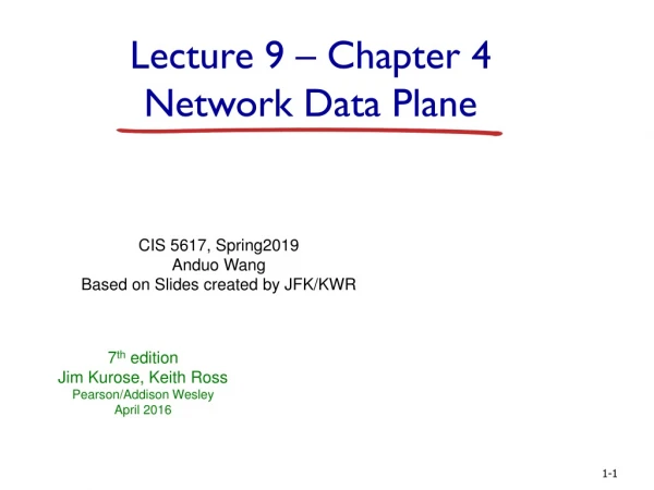
Lecture 9 – Chapter 4 Network Data Plane CIS 5617, Spring2019 Anduo Wang Based on Slides created by JFK/KWR 7th edition Jim Kurose, Keith RossPearson/Addison WesleyApril 2016
4.1 Overview of Network layer data plane control plane 4.2 What’s inside a router 4.3 IP: Internet Protocol datagram format fragmentation IPv4 addressing network address translation IPv6 4.4 Generalized Forward and SDN match action OpenFlow examples of match-plus-action in action Chapter 4: outline Network Layer: Data Plane
high-seed switching fabric Router architecture overview routing, management control plane (software) operates in millisecond time frame routing processor forwarding data plane (hardware) operttes in nanosecond timeframe router input ports router output ports high-level view of generic router architecture: Network Layer: Data Plane
Input port functions lookup, forwarding queueing decentralized switching: • using header field values, lookup output port using forwarding table in input port memory (“match plus action”) • goal: complete input port processing at ‘line speed’ • queuing: if datagrams arrive faster than forwarding rate into switch fabric link layer protocol (receive) switch fabric line termination physical layer: bit-level reception data link layer: e.g., Ethernet see chapter 5 Network Layer: Data Plane
Input port functions lookup, forwarding queueing decentralized switching: • using header field values, lookup output port using forwarding table in input port memory (“match plus action”) • destination-based forwarding: forward based only on destination IP address (traditional) • generalized forwarding: forward based on any set of header field values link layer protocol (receive) switch fabric line termination physical layer: bit-level reception data link layer: e.g., Ethernet see chapter 5 Network Layer: Data Plane
Destination-based forwarding forwarding table Destination Address Range 11001000 00010111 00010000 00000000 through 11001000 00010111 00010111 11111111 11001000 00010111 00011000 00000000 through 11001000 00010111 00011000 11111111 11001000 00010111 00011001 00000000 through 11001000 00010111 00011111 11111111 otherwise Link Interface 0 1 2 3 Q: but what happens if ranges don’t divide up so nicely? Network Layer: Data Plane
Longest prefix matching longest prefix matching when looking for forwarding table entry for given destination address, use longest address prefix that matches destination address. Link interface 0 1 2 3 Destination Address Range 11001000 00010111 00010*** ********* 11001000 00010111 00011000 ********* 11001000 00010111 00011*** ********* otherwise examples: which interface? DA: 11001000 00010111 00010110 10100001 which interface? DA: 11001000 00010111 00011000 10101010 Network Layer: Data Plane
Longest prefix matching • we’ll see why longest prefix matching is used shortly, when we study addressing • longest prefix matching: often performed using ternary content addressable memories (TCAMs) • content addressable: present address to TCAM: retrieve address in one clock cycle, regardless of table size • Cisco Catalyst: can up ~1M routing table entries in TCAM Network Layer: Data Plane
Switching fabrics • transfer packet from input buffer to appropriate output buffer • switching rate: rate at which packets can be transfer from inputs to outputs • often measured as multiple of input/output line rate • N inputs: switching rate N times line rate desirable • three types of switching fabrics memory bus memory crossbar Network Layer: Data Plane
4.1 Overview of Network layer data plane control plane 4.2 What’s inside a router 4.3 IP: Internet Protocol datagram format fragmentation IPv4 addressing network address translation IPv6 4.4 Generalized Forward and SDN match action OpenFlow examples of match-plus-action in action Chapter 4: outline Network Layer: Data Plane
host, router network layer functions: • IP protocol • addressing conventions • datagram format • packet handling conventions forwarding table The Internet network layer transport layer: TCP, UDP • routing protocols • path selection • RIP, OSPF, BGP network layer • ICMP protocol • error reporting • router “signaling” link layer physical layer Network Layer: Data Plane
IP protocol version number 32 bits total datagram length (bytes) header length (bytes) type of service head. len ver length for fragmentation/ reassembly fragment offset “type” of data flgs 16-bit identifier max number remaining hops (decremented at each router) upper layer time to live header checksum 32 bit source IP address 32 bit destination IP address upper layer protocol to deliver payload to e.g. timestamp, record route taken, specify list of routers to visit. options (if any) data (variable length, typically a TCP or UDP segment) IP datagram format how much overhead? • 20 bytes of TCP • 20 bytes of IP • = 40 bytes + app layer overhead Network Layer: Data Plane
network links have MTU (max.transfer size) - largest possible link-level frame different link types, different MTUs large IP datagram divided (“fragmented”) within net one datagram becomes several datagrams “reassembled” only at final destination IP header bits used to identify, order related fragments … … reassembly IP fragmentation, reassembly fragmentation: in: one large datagram out: 3 smaller datagrams Network Layer: Data Plane
length =1040 length =4000 length =1500 length =1500 ID =x ID =x ID =x ID =x fragflag =0 fragflag =1 fragflag =0 fragflag =1 offset =0 offset =370 offset =0 offset =185 one large datagram becomes several smaller datagrams IP fragmentation, reassembly example: • 4000 byte datagram • MTU = 1500 bytes 1480 bytes in data field offset = 1480/8 Network Layer: Data Plane
4.1 Overview of Network layer data plane control plane 4.2 What’s inside a router 4.3 IP: Internet Protocol datagram format fragmentation IPv4 addressing network address translation IPv6 4.4 Generalized Forward and SDN match action OpenFlow examples of match-plus-action in action Chapter 4: outline Network Layer: Data Plane
IP address: 32-bit identifier for host, router interface interface: connection between host/router and physical link router’s typically have multiple interfaces host typically has one or two interfaces (e.g., wired Ethernet, wireless 802.11) IP addresses associated with each interface 223.1.1.2 223.1.3.27 IP addressing: introduction 223.1.1.1 223.1.2.1 223.1.1.4 223.1.2.9 223.1.1.3 223.1.2.2 223.1.3.2 223.1.3.1 223.1.1.1 = 11011111 00000001 00000001 00000001 223 1 1 1 Network Layer: Data Plane
Q: how are interfaces actually connected? A: we’ll learn about that in chapter 5, 6. 223.1.1.2 223.1.3.27 IP addressing: introduction 223.1.1.1 223.1.2.1 223.1.1.4 223.1.2.9 223.1.1.3 223.1.2.2 A: wired Ethernet interfaces connected by Ethernet switches 223.1.3.2 223.1.3.1 For now: don’t need to worry about how one interface is connected to another (with no intervening router) A: wireless WiFi interfaces connected by WiFi base station Network Layer: Data Plane
IP address: subnet part - high order bits host part - low order bits what’s a subnet ? device interfaces with same subnet part of IP address can physically reach each other without intervening router subnet Subnets 223.1.1.1 223.1.2.1 223.1.1.2 223.1.1.4 223.1.2.9 223.1.2.2 223.1.3.27 223.1.1.3 223.1.3.2 223.1.3.1 network consisting of 3 subnets Network Layer: Data Plane
recipe to determine the subnets, detach each interface from its host or router, creating islands of isolated networks each isolated network is called a subnet 223.1.1.0/24 223.1.2.0/24 223.1.1.1 223.1.2.1 223.1.1.2 223.1.1.4 223.1.2.9 223.1.2.2 223.1.3.27 223.1.1.3 223.1.3.2 223.1.3.1 223.1.3.0/24 subnet Subnets subnet mask: /24 Network Layer: Data Plane
how many? Subnets 223.1.1.2 223.1.1.1 223.1.1.4 223.1.1.3 223.1.7.0 223.1.9.2 223.1.9.1 223.1.7.1 223.1.8.1 223.1.8.0 223.1.2.6 223.1.3.27 223.1.2.1 223.1.2.2 223.1.3.1 223.1.3.2 Network Layer: Data Plane
IP addressing: CIDR CIDR:Classless InterDomain Routing • subnet portion of address of arbitrary length • address format: a.b.c.d/x, where x is # bits in subnet portion of address host part subnet part 11001000 00010111 00010000 00000000 200.23.16.0/23 Network Layer: Data Plane
IP addresses: how to get one? Q: How does a host get IP address? • hard-coded by system admin in a file • Windows: control-panel->network->configuration->tcp/ip->properties • UNIX: /etc/rc.config • DHCP:Dynamic Host Configuration Protocol: dynamically get address from as server • “plug-and-play” Network Layer: Data Plane
IP addresses: how to get one? Q: how does network get subnet part of IP addr? A: gets allocated portion of its provider ISP’s address space ISP's block 11001000 00010111 00010000 00000000 200.23.16.0/20 Organization 0 11001000 00010111 00010000 00000000 200.23.16.0/23 Organization 1 11001000 00010111 00010010 00000000 200.23.18.0/23 Organization 2 11001000 00010111 00010100 00000000 200.23.20.0/23 ... ….. …. …. Organization 7 11001000 00010111 00011110 00000000 200.23.30.0/23 Network Layer: Data Plane
200.23.16.0/23 200.23.18.0/23 200.23.30.0/23 200.23.20.0/23 . . . . . . Hierarchical addressing: route aggregation hierarchical addressing allows efficient advertisement of routing information: Organization 0 Organization 1 “Send me anything with addresses beginning 200.23.16.0/20” Organization 2 Fly-By-Night-ISP Internet Organization 7 “Send me anything with addresses beginning 199.31.0.0/16” ISPs-R-Us Network Layer: Data Plane
200.23.16.0/23 200.23.18.0/23 200.23.30.0/23 200.23.20.0/23 . . . . . . Hierarchical addressing: more specific routes ISPs-R-Us has a more specific route to Organization 1 Organization 0 “Send me anything with addresses beginning 200.23.16.0/20” Organization 2 Fly-By-Night-ISP Internet Organization 7 “Send me anything with addresses beginning 199.31.0.0/16 or 200.23.18.0/23” ISPs-R-Us Organization 1 Network Layer: Data Plane
NAT: network address translation rest of Internet local network (e.g., home network) 10.0.0/24 10.0.0.1 10.0.0.4 10.0.0.2 138.76.29.7 10.0.0.3 datagrams with source or destination in this network have 10.0.0/24 address for source, destination (as usual) alldatagrams leaving local network have same single source NAT IP address: 138.76.29.7,different source port numbers Network Layer: Data Plane
NAT: network address translation motivation: local network uses just one IP address as far as outside world is concerned: • range of addresses not needed from ISP: just one IP address for all devices • can change addresses of devices in local network without notifying outside world • can change ISP without changing addresses of devices in local network • devices inside local net not explicitly addressable, visible by outside world (a security plus) Network Layer: Data Plane
NAT: network address translation implementation: NAT router must: • outgoing datagrams:replace (source IP address, port #) of every outgoing datagram to (NAT IP address, new port #) . . . remote clients/servers will respond using (NAT IP address, new port #) as destination addr • remember (in NAT translation table)every (source IP address, port #) to (NAT IP address, new port #) translation pair • incoming datagrams:replace (NAT IP address, new port #) in dest fields of every incoming datagram with corresponding (source IP address, port #) stored in NAT table Network Layer: Data Plane
3 1 2 4 S: 10.0.0.1, 3345 D: 128.119.40.186, 80 S: 138.76.29.7, 5001 D: 128.119.40.186, 80 1:host 10.0.0.1 sends datagram to 128.119.40.186, 80 2:NAT router changes datagram source addr from 10.0.0.1, 3345 to 138.76.29.7, 5001, updates table S: 128.119.40.186, 80 D: 10.0.0.1, 3345 S: 128.119.40.186, 80 D: 138.76.29.7, 5001 NAT: network address translation NAT translation table WAN side addr LAN side addr 138.76.29.7, 5001 10.0.0.1, 3345 …… …… 10.0.0.1 10.0.0.4 10.0.0.2 138.76.29.7 10.0.0.3 4:NAT router changes datagram dest addr from 138.76.29.7, 5001 to 10.0.0.1, 3345 3:reply arrives dest. address: 138.76.29.7, 5001 * Check out the online interactive exercises for more examples: http://gaia.cs.umass.edu/kurose_ross/interactive/ Network Layer: Data Plane
NAT: network address translation • 16-bit port-number field: • 60,000 simultaneous connections with a single LAN-side address! • NAT is controversial: • routers should only process up to layer 3 • address shortage should be solved by IPv6 • violates end-to-end argument • NAT possibility must be taken into account by app designers, e.g., P2P applications • NAT traversal: what if client wants to connect to server behind NAT? Network Layer: Data Plane
4.1 Overview of Network layer data plane control plane 4.2 What’s inside a router 4.3 IP: Internet Protocol datagram format fragmentation IPv4 addressing network address translation IPv6 4.4 Generalized Forward and SDN match action OpenFlow examples of match-plus-action in action Chapter 4: outline Network Layer: Data Plane
IPv6: motivation • initial motivation:32-bit address space soon to be completely allocated. • additional motivation: • header format helps speed processing/forwarding • header changes to facilitate QoS IPv6 datagram format: • fixed-length 40 byte header • no fragmentation allowed Network Layer: Data Plane
IPv6 datagram format priority: identify priority among datagrams in flow flow Label: identify datagrams in same “flow.” (concept of“flow” not well defined). next header: identify upper layer protocol for data pri ver flow label hop limit payload len next hdr source address (128 bits) destination address (128 bits) data 32 bits Network Layer: Data Plane
Other changes from IPv4 • checksum:removed entirely to reduce processing time at each hop • options: allowed, but outside of header, indicated by “Next Header” field • ICMPv6: new version of ICMP • additional message types, e.g. “Packet Too Big” • multicast group management functions Network Layer: Data Plane
IPv6 header fields IPv6 source dest addr UDP/TCP payload IPv4 payload Transition from IPv4 to IPv6 • not all routers can be upgraded simultaneously • no “flag days” • how will network operate with mixed IPv4 and IPv6 routers? • tunneling: IPv6 datagram carried as payload in IPv4 datagram among IPv4 routers IPv4 header fields IPv4 source, dest addr IPv6 datagram IPv4 datagram Network Layer: Data Plane
IPv4 tunnel connecting IPv6 routers logical view: A A E E B B F F IPv6 IPv6 IPv6 IPv6 IPv6 IPv6 IPv6 IPv6 Tunneling C D physical view: IPv4 IPv4 Network Layer: Data Plane
Flow: X Src: A Dest: F data Flow: X Src: A Dest: F data IPv4 tunnel connecting IPv6 routers logical view: A A E E B B F F IPv6 IPv6 IPv6 IPv6 IPv6 IPv6 IPv6 IPv6 src:B dest: E src:B dest: E flow: X src: A dest: F data flow: X src: A dest: F data A-to-B: IPv6 E-to-F: IPv6 B-to-C: IPv6 inside IPv4 B-to-C: IPv6 inside IPv4 Tunneling C D physical view: IPv4 IPv4 Network Layer: Data Plane
IPv6: adoption • Google: 8% of clients access services via IPv6 • NIST: 1/3 of all US government domains are IPv6 capable • Long (long!) time for deployment, use • 20 years and counting! • think of application-level changes in last 20 years: WWW, Facebook, streaming media, Skype, … • Why? Network Layer: Data Plane
4.1 Overview of Network layer data plane control plane 4.2 What’s inside a router 4.3 IP: Internet Protocol datagram format fragmentation IPv4 addressing network address translation IPv6 4.4 Generalized Forward and SDN match action OpenFlow examples of match-plus-action in action Chapter 4: outline Network Layer: Data Plane
Generalized Forwarding and SDN Each router contains a flow table that is computed and distributed by a logically centralized routing controller logically-centralized routing controller local flow table headers counters actions control plane data plane 1 0100 1101 2 3 values in arriving packet’s header Network Layer: Data Plane
OpenFlow data plane abstraction Flow table in a router (computed and distributed by controller) define router’s match+action rules • flow: defined by header fields • generalized forwarding: simple packet-handling rules • Pattern: match values in packet header fields • Actions: for matched packet: drop, forward, modify, matched packet or send matched packet to controller • Priority: disambiguate overlapping patterns • Counters: #bytes and #packets Network Layer: Data Plane
OpenFlow data plane abstraction * : wildcard • src=1.2.*.*, dest=3.4.5.* drop • src = *.*.*.*, dest=3.4.*.* forward(2) • 3. src=10.1.2.3, dest=*.*.*.* send to controller • flow: defined by header fields • generalized forwarding: simple packet-handling rules • Pattern: match values in packet header fields • Actions: for matched packet: drop, forward, modify, matched packet or send matched packet to controller • Priority: disambiguate overlapping patterns • Counters: #bytes and #packets
OpenFlow: Flow Table Entries Rule Action Stats Packet + byte counters • Forward packet to port(s) • Encapsulate and forward to controller • Drop packet • Send to normal processing pipeline • Modify Fields Eth type Switch Port IP Src IP Dst IP Prot TCP sport TCP dport VLAN ID MAC src MAC dst Transport layer Network layer Link layer
Examples Switch Port Switch Port Switch Port MAC src MAC src MAC src MAC dst MAC dst MAC dst Eth type Eth type Eth type VLAN ID VLAN ID VLAN ID IP Src IP Src IP Src IP Dst IP Dst IP Dst IP Prot IP Prot IP Prot TCP sport TCP sport TCP sport TCP dport TCP dport TCP dport Forward Action Forward Destination-based forwarding: 51.6.0.8 * * * * * * * * * port6 IP datagrams destined to IP address 51.6.0.8 should be forwarded to router output port 6 Firewall: * * * * * * * * * 22 drop do not forward (block) all datagrams destined to TCP port 22 drop 128.119.1.1 * * * * * * * * * do not forward (block) all datagrams sent by host 128.119.1.1
Examples Switch Port MAC src MAC dst Eth type VLAN ID IP Src IP Dst IP Prot TCP sport TCP dport Action Destination-based layer 2 (switch) forwarding: 22:A7:23: 11:E1:02 * * * * * * * * * port3 layer 2 frames from MAC address 22:A7:23:11:E1:02 should be forwarded to output port 6 Network Layer: Data Plane
OpenFlow abstraction • match+action: unifies different kinds of devices • Router • match: longest destination IP prefix • action: forward out a link • Switch • match: destination MAC address • action: forward or flood • Firewall • match: IP addresses and TCP/UDP port numbers • action: permit or deny • NAT • match: IP address and port • action: rewrite address and port Network Layer: Data Plane
OpenFlow example Example: datagrams from hosts h5 and h6 should be sent to h3 or h4, via s1 and from there to s2 Host h6 10.3.0.6 controller s3 1 2 4 3 Host h5 10.3.0.5 s1 s2 1 match match match action action action 1 Host h4 10.2.0.4 2 ingress port = 2 IP Dst = 10.2.0.3 ingress port = 2 IP Dst = 10.2.0.4 ingress port = 1 IP Src = 10.3.*.* IP Dst = 10.2.*.* IP Src = 10.3.*.* IP Dst = 10.2.*.* 4 4 2 forward(3) forward(3) Host h1 10.1.0.1 forward(4) 3 3 Host h2 10.1.0.2 forward(4) Host h3 10.2.0.3
Chapter 4: done! Question: how do forwarding tables (destination-based forwarding) or flow tables (generalized forwarding) computed? Answer: by the control plane (next chapter) 4.1 Overview of Network layer: data plane and control plane 4.2 What’s inside a router 4.3 IP: Internet Protocol • datagram format • fragmentation • IPv4 addressing • NAT • IPv6 4.4 Generalized Forward and SDN • match plus action • OpenFlow example Network Layer: Data Plane