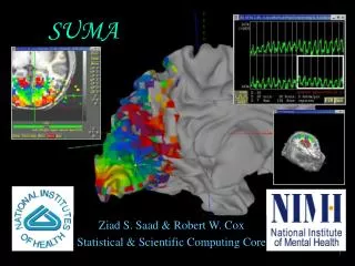
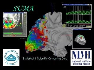
SUMA
SUMA is a versatile surface mapping and analysis tool tightly linked to AFNI. It supports 2D and 3D object representation, offering various analysis functions like time series analysis, smoothing, statistics, and clustering. The process involves data collection, alignment, surface creation, alignment, and mapping experimental data to surfaces.

SUMA
E N D
Presentation Transcript
SUrface MApping with AFNI • Surface mapping & viewing program tightly linked to AFNI • Complements AFNI’s slice and volume rendering modes • Provides a framework for fast and user-customizable surface based analysis • Supports surface models created by: FreeSurfer http://surfer.nmr.mgh.harvard.edu SureFit/Caret http://stp.wustl.edu/resources/display.html BrainVoyager http://www.brainvoyager.com • Allows representation of 2D and 3D objects in projection frame or surface coordinate space.
The Process • PreSUMA: • Collect, align and average high-quality, high-resolution anatomical data • On NIMH’s 3T-1, 4 MPRAGE data sets will do • Correct image non-uniformity • Using AFNI’s 3dUniformize or the N3 normalization tool [J.G. Sled et al. 98] • Create and correct surfaces • Using FreeSurfer, SureFit or BrainVoyager • CircumSUMA: • Create standard-mesh version of surface models • Align surface with experimental data • Using @SUMA_AlignToExperiment • Map experimental volumetric data to surface • Using AFNI and SUMA • Time series analysis • Smoothing, statistics, clustering, group analysis.
The Lesser Process • For display (mostly) of Talairach data: • Use the Talairach surfaces created from the N27 brain data set using FreeSurfer. • Ready to use, no surface creation or alignment needed.
A: Preparing surface models for SUMA Create Surface Models (FreeSurfer, Caret, etc.) High-Res. Anatomical MRI data @SUMA_Make_Spec_* Spec File ASCII file defining relationships between different surfaces SurfVol AFNI-format Surface Volume that is aligned with surface models
@SUMA_Make_Spec_* scripts • These scripts prepare surfaces and volumes for use with SUMA: • @SUMA_Make_Spec_FS for FreeSurfer surfaces • @SUMA_Make_Spec_SF for SureFit surfaces • @SUMA_Make_Spec_Caret for Caret surfaces • Output of these scripts include: • Surface Volume: SurfVol • An AFNI data set created from anatomical MRI used to create the surfaces • AFNI volumes of cortical and subcortical segmentations (FreeSurfer) • ASCII versions of all surfaces (FreeSurfer) • Surface specifications file: (*.spec) • An ASCII file defining relationships between family of surfaces.
Viewing Surfaces with SUMA • After @SUMA_Make_Spec_* scripts are run, surface models should be in excellent alignment with SurfVol • Use SUMA to verify alignment • Scroll through the volume to make sure surfaces are accurate • Check especially for inferior temporal and occipital areas • Demo using FreeSurfer surfaces: • cd suma_demo/SurfData/SUMA • This is where the output of @SUMA_Make_Spec_FS resides • afni –niml & • launches AFNI to allow the viewing of DemoSubj_lh.spec • the –niml option tells AFNI to listen to connections from SUMA • suma –spec DemoSubj_lh.spec –sv DemoSubj_SurfVol+orig & • or execute the script: tcsh run_suma Hands-On
Check for proper alignment and defects • With both SUMA and AFNI running • Press ‘t’ in the suma window to ‘talk’ to AFNI • This sends anatomically correct surface to AFNI • Switch Underlay to DemoSubj_SurfVol+orig • Contours are the intersection of the surface with the volume. • You could also see boxes representing the nodes that are within +/- 1/2slice from the center of the slice in view. • Colors and node box visibility can be changed to suit your fancy from the Control Surface button in AFNI. • Navigate through the volume in AFNI. • make sure you have an excellent alignment between volume and surface • make sure surface adequately represents areas of the brain that are difficult to segment • occipital cortex • inferior frontal and inferior temporal regions Hands-On
Check for proper alignment and defects • The Surface Volume and the surfaces must be in perfect alignment. • If you have an improper alignment, it should be addressed here. • This should not happen for FreeSurfer and SureFit surfaces created in the standard fashion. • Watch for error messages and warnings that come up in the shell as the surfaces are read in. These messages should be screened once since they do not change unless the surface’s geometry or topology is changed. • Viewed without the volume underlay, it is extremely difficult to tell if surface models with no topological defects accurately represent the cortical surface. Hands-On
Basic SUMA viewer functions • Rotating the surface: • Mouse button-1: keep it down while moving the mouse left to right. This rotates the surface about the screen's Y-axis (dotted green). Let go of button-1. • Repeat with up and down motion for rotation about X-axis and motion in various directions for rotations mimicking those of a trackball interface. • Also try up/down/left/right arrow keys. • Arrow keys rotate by increments specified by the environment variable: SUMA_ArrowRotAngle (degrees). Hands-On
Basic SUMA viewer functions • Translating the surface: • Mouse button-2: keep it down while moving the mouse to translate surface along screen X and Y axes or any combinations of the two. • Also try shift+arrow keys. • Zooming in/out: • Both buttons 1&2 or Shift + button 2: while pressing buttons, move mouse down or up to zoom in and out, respectively. • Also try keyboard buttons 'Z' and 'z' for zooming in and out, respectively. Hands-On
Basic SUMA viewer functions • Picking a Node or Facet: • Mouse button 3: press over a location on a surface to pick the closest facet and node to the location of the pointer. • The closest node is highlighted with a blue sphere • The closest facet is highlighted with a gray triangle • Note the information written to the shell regarding the properties of the picked Node and Facet. • When connected to AFNI (after having pressed ‘t’), watch the AFNI crosshair jump to the corresponding location in the volume. • Conversely, position the crosshair in AFNI (left click) at a position close to the surface and watch the crosshair relocate in SUMA. • You can swap button 1 & 3’s functions using the environment variable: SUMA_SwapButtons_1_3 Hands-On
Basic SUMA viewer functions • Cardinal views: • ctrl + Left/Right: Views along LR axis • ctrl + Up/Down: Views along SI axis • ctrl + shift + Up/down: Views along AP axis • Resetting the view point: • Press Home to get back to the original vantage point. • Using momentum feature: • Press ‘m’ to toggle momentum on. Click the left mouse button and release the button as you are dragging the mouse. • Lots more: • Function keys modify various aspects of the display • ctrl+h opens a help window for all interactive options. Hands-On
Recording your rendered images • Using ‘r’ in SUMA to record the current scene. • Using ‘r’ on the colorbar creates an image of the colorbar. • Using ‘R’ to record continuously the rendered scene. • Images are captured by an AFNIesque viewer. • Identical consecutive images are rejected • Images caused by X expose events are ignored • Images can be saved in all ways allowed by AFNI, including MPEG and animated GIF • If you let the recorder run continuously with very large images, you might quickly run out of memory • You can save/load viewer setting used to create figure • Use ‘FileSave’ View and ‘FileLoad View’ Hands-On
world AFNI SUMA world • AFNI and SUMA are independent programs and communicate using NIML formatted data elements • Via shared memory or network sockets • Both AFNI and SUMA can also communicate with other programs • NIML: NeuroImaging Markup Language developed by Dr. R.W. Cox • NIML is the main format for SUMA’s data storage • NIML API library for packing/unpacking data is available • Protocol allows independent program to communicate with AFNI • Advantages include: • Programs execute on separate machines • Fast development • Screen real-estate • Blemishes include: • Only one AFNI can be listening for connections • Only one SUMA can connect to AFNI
What’s a surface made of? Node Edge
Relationships between surface models • Surface Geometry: • refers to the spatial coordinates of nodes forming a surface model • Surface Topology: • refers to the connectivity between nodes forming a surface model • A family of surfaces with different geometry but similar topology is created for each surface model. • white/grey, pial, inflated, spherical, flattened, etc. • Some models’ geometries are anatomically correct • Pial and/or white matter surfaces can be used for relating to volume data. • Inflated, flattened and spherical cannot be directly linked to volume data. The link is done via their corresponding anatomically-correct surfaces. • Those relationships are encoded in the Spec file.
Geometry and Topology • Geometry: Spatial location • X,Y,Z coordinates of brain structures • Topology: Spatial connectivity • Relative positions of brain structures along the surface • Geometric proximity does not imply topological proximity • If you care about the topology of activation, you should transfer FMRI data onto the surface before spatial manipulations of the data
SmoothWm Inflated Spherical Inflated, Occipital cut Pial Overlay of anatomically correct Pial and SmoothWm surfaces over anatomical volume Flattened, Occipital cut
Viewing the group of surfaces • Switch Viewing States: • '.' switches to the next viewing state (pial then inflated etc.) • ',' switches to the previous viewing state • Navigate on any of the surfaces and watch AFNI’s crosshair track surface • SPACE toggles between current state and Mapping Reference state • Viewing multiple states concurrently: • ‘ctrl+n’ opens a new SUMA controller (up to 6 allowed, more possible but ridiculous) • switch states in any of the viewers • all viewers are still connected to AFNI Hands-On
Viewing the group of surfaces • Controlling link between viewers: • Open SUMA controller with ‘ctrl+u’ or View->SUMA Controller • SUMA controller crosshair locking options: • ‘-’: no locking • ‘i’: node index locking (i.e. topology based) • ‘c’: node coordinate locking (i.e. geometry based) • SUMA controller view point locking • ‘v’: depress toggle button to link view point across viewers. • Surface rotation and translation in one viewer is reflected in all linked viewers Hands-On
Standardizing Surfaces For Group Analysis • Now that surfaces have been checked for quality, we will transform them for group analysis • This step is the equivalent of standard-space normalization for volume-based analysis. Hands-On
Group analysis • Group analysis requires data defined over a domain common to all subjects • Talairach space for volume-based analysis • With low order registration + Small amount of geometric distortion • No respect for topology of activation • With high order registration + Preserves the topology of action - Considerable geometric distortion • Spherical coordinate system for surface-based analysis + Preserves the topology of activation • Considerable geometric distortion • Preserving the topology of activation is Good in general and crucial for • Retinotopy • Plasticity • High-resolution Mapping
Spherical Warping Surface-based warping is more accurate than the more common low order Talairach volume-based analysis because it preserves the topology of the cortical sheet and uses more landmarks for the warping
Mapping data Problem is that surfaces from different subjects are not topologically isomorphic (different meshes). Data from each subject are mapped onto the icosahedral surface for group analysis Cumbersome and unnecessary interpolation n1 n2 n3
Our twist Instead of interpolating data values to the icosahedral nodes, interpolate using the coordinates of the original surface’s node. This results in a surface that is virtually identical in geometry to the original surface but with the mesh of the icosahedron. Cross-subject surface based analysis is thus reduced to node-based analysis
Standard meshes for 6 subjects • 6 standard-mesh surface models from different subjects. • Node colors encode for node index n on the standard mesh. • Nodes with similar indices correspond to comparable sulcal landmarks despite anatomical variability across subjects.
Original-mesh versions of standard-mesh surfaces with same coloration scheme • Surfaces have differing numbers of nodes, some colors may not be represented • Nodes with similar indices no longer correspond to comparable anatomical areas • Small clusters of red color show new nodes later added to correct topological errors
Creating Standard-Mesh Surfaces • Required Data: • Original Surface models • Warped Spherical surface • Spec file of the surfaces above (i.e. DemoSubj_lh.spec) • Creating the standard-mesh versions of the original surfaces • MapIcosahedron -spec Demo_Subj_lh.spec \ Written by B. Argall • -ld 141 \ • -prefix ld141 • -spec SpecFile: option specifying spec file with original surfaces • -ld n : number of subdivisions for each edge of the icosahedron. • Nv = 2 + 10n2 (198812 vertices) • Nt = 20n2 (397620 triangles) • Ne = 30n2 (596430 edges) • -prefix: prefix assigned to standard mesh surfaces • Script run_stdmeshes was used to generate standard-mesh surfaces for the hands-on material
Using Standard-Mesh Surfaces • Subsequent analysis will use standard-mesh surfaces, not originals • Map single-subject data to corresponding standard-mesh surfaces. • Use any of AFNI’s voxel-based statistical tools to perform within- and cross-subject analysis in the surface domain • Creating standard-mesh surfaces takes a couple of minutes per subject • You can compare original and standard surfaces using: • SUMA • create a spec file containing both original and standard-mesh surfaces. • open two views, one showing original surface and one showing standard-mesh surfaces • link viewers by coordinates (not by node index) from the SUMA controller (ctrl+u) • CompareSurfacesWritten by Shruti Japee • a program that calculates the distance from each node on surface 1 along its normal to surface 2 • SurfaceMetrics • a program that calculates metrics of the mesh like edge lengths, triangle areas, curvature, etc.
Artifacts with standard meshes • In the past, there have been localized distortions between the standard-mesh surface and the original surface. • These had all been caused by topological errors in the original spherical surfaces. • SurfQual was written to highlight these errors • if causing distortions, errors must be fixed with the program used to generate them. • These topological errors can be ignored if they do not cause any visible distortions in the standard-mesh surfaces.
B: Aligning Surface w/ Experiment Data Anatomically correct surface SurfVol Surface Volume @SUMA_AlignToExperiment SurfVol_Alnd_Exp (SurfVol Aligned to ExpVol W/ Alignment Xform) Apply Alignment Xform ExpVol Experiment Volume Func. 1 AFNI Cortical Surface Aligned to Experiment data Func. 2 Func. N
B: Aligning Surface w/ Experiment Data • Functional data are assumed to be in register with experiment’s anatomical • Align Anatomical to EPI using: align_epi_anat.py. • Surface Volume is aligned to experiment’s anatomical volume with rigid-body or affine transformation • The script @SUMA_AlignToExperiment simplifies this step and rarely fails. If it does, you could try manual registration with 3dTagalign • Brain coverage and image types should be comparable, not necessarily identical • Functional data are not interpolated
B: Aligning Surface w/ Experiment Data • Demo: (close previous SUMA and AFNI sessions) • cd suma_demo/afni • DemoSubj_spgrax+orig (experiment’s high-res. anatomical scan) • DemoSubj_EccExpavir+orig & DemoSubj_EccExpavir.DEL+orig (EPI timeseries and function.) • To perform the alignment we ran: @SUMA_AlignToExperiment \ -exp_anat DemoSubj_spgrsa+orig \ -surf_anat ../SurfData/SUMA/DemoSubj_SurfVol+orig • This script 3dvolreg or 3dAllineate to align the experiment’s anatomical volume to the Surface Volume. • The script takes care of resampling (with 3dresample) the experiment’s anatomical volume to match the Surface Volume if need be. • The output volume is named with the prefix of the Surface Volume with the suffix _Alnd_Exp (read Aligned to Experiment). Hands-On
B: Aligning Surface w/ Experiment Data • Launch AFNI to check that volumes aligned well: • afni –niml & • Switch Underlay to DemoSubj_SurfVol_Alnd_Exp+orig • Switch Overlay to DemoSubj_spgrsa+orig • Visually check the alignment: • For example, with pointer in slice viewing window: • press 'o' on the keyboard to turn off the overlay • press 'u' repeatedly to toggle between the two volumes • Launch SUMA to check alignment of surface with volumes suma –spec ../SurfData/SUMA/std.DemoSubj_lh.spec \ –sv DemoSubj_SurfVol_Alnd_Exp+orig & • or execute the script: tcsh run_suma Press ‘t’ to talk to AFNI • You should see a surface overlaid onto DemoSubj_SurfVol_Alnd_Exp+orig • Alignment should be proper, otherwise you have a problem. Hands-On
C: Mapping FMRI Data Onto Surface SUMA A Create Surface Models SurfVol B Align To Experiment Alignment Xform Apply Alignment Xform ExpVol Func. 1 AFNI C Func. 2 Mapping Engine Func. N
Mapping Options • Surface/volume Intersection • Shell/volume Intersection
Mapping options (Pial surface) (Gray/White matter surface) • Surface/volume Intersection • One voxel per node • Shell/volume Intersection • Multiple voxels possible per node
Mapping Habits • When mapping data from volume to surface domains • If mapping assigns multiple voxels to one node • How do you deal with functional data sets? • Do you average statistics? • Do you apply a threshold before or after averaging? • What if some of the voxels are active and some are not? • These problems are best avoided by: • Mapping the time series data onto the surface • Performing statistical analysis directly in the surface domain using 3dSomething AFNI programs • When combining surface data across subjects • Same concerns as with volumetric group analysis • You can also create volumetric data from surface-based data • use 3dSurf2Vol, the reciprocal of 3dVol2Surf
Interactive Mapping Onto Surface • Interactive mapping is controlled by AFNI’s Vol2Surf plugin • Mapping is done using anatomically correct surfaces sent to AFNI with the overlay data volume. • See plugin’s help for details. • Only colors (not data values) are sent from AFNI to SUMA. • Demo (Continued): To map data from volume to surface interactively: • Switch Overlay to DemoSubj_EccExpavir.DEL • Define Overlay with: • Olay: Delay • Thr: Corr. Coef. • Pos. color mapping • #20 color map • See Function • You should see the function on the surface model in SUMA. • The colors are applied to all topologically related surfaces • NOTE: Only AFNI controller A sends function back to SUMA • Change threshold in AFNI and watch change in SUMA Hands-On
Command-line Mapping • 3dVol2Surf maps data directly onto the cortical surface 3dVol2Surf -spec ../SurfData/SUMA/std.DemoSubj_lh.spec \ -surf_A lh.smoothwm.asc \ -surf_B lh.pial.asc \ -sv DemoSubj_SurfVol_Alnd_Exp+orig \ -grid_parent DemoSubj_EccExpavir.DEL+orig \ -map_func ave \ -f_steps 10 \ -f_index nodes \ -out_niml v2s.DEL.niml.dset Written by Rick Reynolds (see output of 3dVol2Surf -help for details.) • Execute script tcsh run_3dVol2Surf to map various types of data onto the surfaces Hands-On
Options for 3dVol2Surf example • Basic Parameters: -spec: SUMA spec file containing surface(s) to be used in mapping. -surf_A (-surf_B): Surface(s) to be used in the mapping. -sv: Surface Volume used to align surface to data -grid_parent: AFNI volume containing data to be mapped. -map_func: Method for handling voxels to node mapping -out_niml: Output data set file in NIML format • Optional parameters (just a few of them): -cmask: Option for masking data in DataVol on the fly.. -oom_value V0 : Assign V0 to nodes in masked voxels -oob_value V1: Assign V1 to nodes that are not covered by any voxels -oom_value and -oob_value are useful for creating ‘full’ datasets.
Format of surface-based datasets • The output dataset can be thought of as a table of numbers. • Each column represents data from one sub-brick in the volume • Each row represents values mapped to a node • By default, a surface dataset is ‘sparse’; containing only rows for the nodes that had data mapped onto them • When combining surface-based datasets, it is safest to work with ‘full’ datasets which contain a row for each node • ConvertDset can turn ‘sparse’ datasets into ‘full’ ones. • Useful tools for manipulating datasets: • 3dinfo (Information as viewed by AFNI’s 3d* progams) • SurfDsetInfo (Information as viewed by SUMA) • ConvertDset (A tool to convert between formats) • Selection qualifiers to dataset names • [SEL] to select certain columns (sub-bricks) • {SEL} to select certain rows • #SEL# to select certain nodes • The format of SEL is the same as in AFNI, see section 'INPUT DATASET NAMES' in 3dcalc -help for details. • [i] to select the node index column (NIML dsets only)
Colorizing Results Interactively • Demo (continued): • In SUMA, press ‘ctrl+s’ to open Surface Controller. • Use ViewSurface Controller if you were born after 1981. Hands-On
Graphing Time Series • Demo (continued): • Press “Load Dset” and read in “v2s.TS.niml.dset” • In SUMA, press ‘g’ to graph data points at the selected node • Select other nodes to see data at other nodes • Press ‘Freeze’ on graph window to preserve current graph • Clicking on other nodes will start a new graph That’s a bug Hands-On