Data Modeling Transformation for RDBMS Implementation
380 likes | 489 Vues
Learn how to convert ERD to relational model and handle complex data structures for optimal database design.

Data Modeling Transformation for RDBMS Implementation
E N D
Presentation Transcript
Mapping from Data Model (ERD) to Relational Model Yong Choi School of Business CSUB
Transformation • Transform the conceptual database design (ERD) into a logical database design that can be implemented on a chosen DBMS later (our choice: RDS) • Input: conceptual model (ERD) • Output: relational model (schema), normalized relations
Why do I need to know this? • CASE tools can perform many of the transformation steps automatically, but.. • Often CASE tools cannot model complexity of data and relationship • Example: ternary relationship, supertype and subtype relationship • You must be able to perform a quality check on CASE tool results
Transformation Procedure • An entity turns into a table. • Each attribute turns into a column in the table. • The (unique) identifier of the entity turns into a PK of the table. • In general, the ERD (data model) does not include FK information. • Restaurant database: next slide
Composite and Multi-valued Attributes • An attribute is considered composite if it comprises two or more other attributes. • Divided into atomic and separate attribute • There should no such thing as a multi-valued attribute (phone #) in a relational database. • Against “Set Theory” • “Multi-valued Attribute” must be turned into a new entity of its own…..
Emp_Id PK Emp_Lname Emp_Fname Salary Mapping an entity into a relation • An Entity name: Employee • Attributes: • Emp_ID, Emp_Lname, Emp_Fname, Salary • Identifier: Emp_ID Employee
Mapping an entity into a relation Movies Movies title year length filmType Title Year Length Film Type Star Wars 1977 124 color Mighty Ducks 1991 104 color Wayne’s World 1992 95 color
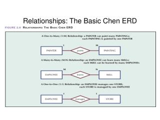
Mapping binary relationships • One-to-one: if there is no indication of optionality, then it needs to be decided by developers. • one-to-one mandatory relationship • Restaurant DB: BillingAddress and Customer • One-to-many: PK on the one side becomes FK on the many side • Many-to-many - create a new relation (bridge entity) with the PKs of the two entities as its composite PK
Mapping a 1:1 relationship with optionality on the one side • Nurse: • Nurse_ID, Name, Date_of_Birth • Care Center • Center_Name, Location, Date_Assigned
Mapping a 1:1 relationship OK to use Nurse_ID Access: - Name must be matched FK: Nurse_ID
Mapping a 1:M relationship • Customer: • Customer_ID, Customer_Name, Customer_Address • Order: • Order_ID, Order_Date
Mapping M:N relationship Each student takes many classes, and a class must be taken by many students. STUDENT CLASS IS_TAKEN_BY TAKE
CLASS Class_Student STUDENT Transformation of M:N • The relational operations become very complex and are likely to cause system efficiency errors and output errors. • Break the M:N down into 1:N and N:1 relationships using bridge entity (weak entity).
Example M:N Relationship Table to represent Entity 3 to 3 30 to 30 300 to 300 3000 to 3000 30,000 to 30,000 300, 000 to 300, 000
Converting M:N Relationship to Two 1:M Relationships Bridge Entity
Mapping an M:N relationship Student Enroll (added later!) Class CLASS_ROOM PROF_NUM
Mapping a bridge entity with its own name and identifier Shipment_NO Customer_ID Vendor_ID Date Amount Customer_ID Name Other Attributes Vendor_ID Address Other Attributes
Mapping composite and Multi-valued attributes to relation • Composite attribute: use only their simple, component attributes – divide into atomic and separate attribute. • Multi-valued attribute: turned it into a new entity of its own…..
Mapping composite attributes to relation Customer Composite attribute Customer_ID Customer_Name Customer_Address
Mapping a multi-valued attribute Employee SSN Name Phone #
Mapping a weak entity • Becomes a separate relation with a FK taken from the regular entity • Primary key composed of: • Partial identifier of weak entity • Primary key of identifying relation
Mapping a weak entity In general, identifier of the regular entity is not included during the modeling
Mapping a weak entity Employee NOTE:The FK of DEPENDENT should NOT allow null value if DEPENDENT is a weak entity Dependent FK
Mapping 1:M recursive (or unary) relationship Employee FK • Manager_ID references Emp_ID
Mapping Supertype/subtype relationship • Create a separate relation for the supertype and each of the subtypes • Assign common attributes to supertype • Assign PK and unique attributes to each subtype • Assign an attribute of the supertype to act as subtype discriminator