Download
1 / 95
950 likes | 1.18k Vues
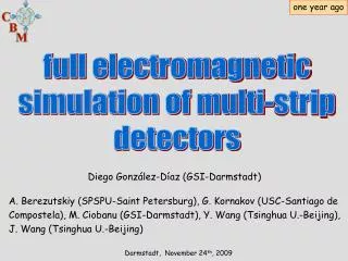
one year ago. full electromagnetic simulation of multi-strip detectors. Diego González-Díaz (GSI-Darmstadt) A. Berezutskiy (SPSPU-Saint Petersburg), G. Kornakov (USC-Santiago de Compostela), M. Ciobanu (GSI-Darmstadt), Y. Wang (Tsinghua U.-Beijing), J. Wang (Tsinghua U.-Beijing).

E N D
one year ago full electromagnetic simulation of multi-strip detectors Diego González-Díaz (GSI-Darmstadt) A. Berezutskiy (SPSPU-Saint Petersburg), G. Kornakov (USC-Santiago de Compostela), M. Ciobanu (GSI-Darmstadt), Y. Wang (Tsinghua U.-Beijing), J. Wang (Tsinghua U.-Beijing) Darmstadt, November 24th, 2009
now RPC simulations for CBM and R3B Diego González-Díaz (GSI, TU Darmstadt, Tsinghua University) Y. Wang (Tsinghua U.-Beijing), J. Wang (Tsinghua U.-Beijing), C. Huangshan (Tsinghua U.-Beijing), P. Kowina (GSI), P. Moritz(GSI) and the NeuLand-R3B group Darmstadt, February 10th, 2011
X workshop on Resistive Plate Chambers and related detectors Darmstadt, February 9-12, 2010. Sponsored by HIC4FAIR.
contributions directly connected to GSI • RPC HADES-TOF wall cosmic ray test performance, A. Blanco. • FOPI MMRPC ToF barrel. M. Kis. • A multipurpose Trigger Readout board. M. Palka. • The Slow Control System of the HADES RPC wall. A. Gil. • High Resolution TDC ASIC for CBM-TOF, H. Flemming.
contributions directly connected to FAIR • Progress of R&D and production of timing RPCs in Tsinghua University, Yi Wang. • A prototype of high rate MRPC for CBM-TOF, J. Wang. • Ceramics high rate MRPC for CBM-TOF, L. Naumann • Towards a high granularity, high counting rate, differential read-out RPC. M. Petris. • The CBM Time-of-Flight wall.I. Deppner. • Progress in the simulation of Resistive Plate Chambers with multi-strip readout.D.Gonzalez-Diaz. • NeuLand: MRPC-based time-of-flight detector for 1 GeV neutrons.D. Bemmerer. • Development of MMRPC prototypes for R3B, FAIR. U. Datta Pramanik. • Some results of the R&D of a ToF-wall to identify relativistic ions.E. Casarejos. • Design and construction of iToF: a ToF-wall detector to identify relativistic ions in R3B,FAIR, E. Casarejos. • A closed-circuit gas-recirculation system for RPC detectors. D. Rossi. • NeuLand MRPC-based detector prototypes tested with fast neutrons. C. Caesar. • Testing timing RPCs at ELBE/Dresden using 32MeV single-electron bunches with picosecond time resolution.D. Stach. • NeuLAND MRPC prototypes tested at ELBE/Dresden.D. Yakorev.
->28%of the workshop contributions were connected to GSI/FAIR. ->70% of the workshop contributions related to time-of-flight ((and)multigap, (and)multistrip) RPCS were connected to GSI/FAIR.
GSI-FAIR in a nutshell (as of today) R3B/neuLand (SIS100) R3B/itof (SIS100) FOPI (SIS18/SIS100) FOPI (SIS18) CBM (SIS100/SIS300)
progress on the simulation and understanding of the counters
The simulation scheme in a nutshell transmission 1 2 generation + induction 4 3 multi-strip FEE response
What is new? • 1. Dedicated measurements of transmission properties and benchmark of the electrostatic solver and modeling: • -Before: APLAC simulations(FDTD). • -Now: MAXWELL-2D(FEM) + analytical solutions of lossy telegrapher's equations. • 2. Calculation of the induction profiles: • -Before: analytical calculation (approximate). • -Now: MAXWELL-2D(FEM). Analytical calculation used only for • benchmarking the code. • 3. Change of philosophy: • -Before: work with induced charges (~slow amplifier). • -Now: work with induced currents (broad-band amplifiers). • 4. More realistic implementation of the Front End Electronics. • 5. New parameters of the gas. MAGBOLTZ cross-sections re-obtained to be • consistent with 2009data for C2H2F4. • 6. A simple parameterization of streamer formation introduced, based on data. • 7. Started porting the code MATLAB-based to C++ for usage in FAIRroot both for R3B and CBM (~50% done).
transmission 2 1. Upgrades in signal transmission
transmission characteristics in frequency-domain transmission near-end cross-talk far-end cross-talk transmission (single-strip)
possibly the most important figure of merit the cross-talk to the over-next neighbor is the relevant figure of merit!
The CBM-TOF wall. Design requirements compensation for N-strips requires of the following conditions: then all the system velocities become equal! (no modal dispersion) generally not satisfied generally satisfied details and proof in: Diego Gonzalez-Diaz, Chen Huangshan, Yi Wang, arXiv.1102.1389
1 induction 2. Upgrades on signal induction and charge profiles
'Weighting field' technique for calculating induction profiles MAXWELL-2D calculation analytic calculation The analytical calculation usually fails in between strips
1 induction 3. Upgrades on avalanche modeling this part is still considerably behind the 'state of the art' simulations (the practical importance of a better modelization is not clear)
Determination of C2H2F4 cross-sections from most recent data. MAGBOLTZ accuracy improved down to 1%. (S. Biagi) now before
Avalanche model constrained by world-wide survey efficiency charge distribution +streamer parameterized in a crude way (when avalanche reaches a certain charge it 'explodes' into a streamer) Diego Gonzalez-Diaz, doi:10.1016/j.nima.2010.09.067
3 FEE response 3. Upgrades on FEE modeling
Upgrades on FEE modeling (based on APLAC) simplified sketch of the FEE developed by the RICE University (STAR) Modeling this is the weakest part so far. Requires hands-on work. Can not be modeled without detailed measurements. The main parameters of the electronics (threshold, gain) are now fixed to describe data
~center of strip ~region between strips modestly fast ~100evts/s • representation • gain=1 • Vth equivalent • at input
two selected chambers 1m-long, 6x2(0.22gap) 24cm-long, 5x2(0.25gap)
Triggered events 24cm-long, 5x2(0.25gap) charge distributions
Triggered events 1m-long, 6x2(0.22gap) charge distributions
Triggered events and RPC fired 1m-long, 6x2(0.22gap) charge distributions
Global response resolution efficiency and cross-talk
multi-strip prototypes for R3B. Transmission. D. Yakorev et al. submited to NIM A
Outlook • A MATLAB toolbox for fast RPC characterization is close to be finished. A fast scheme to simulate these counters has been implemented. • With a larger scope, a software package is being created and integrated in FAIRroot. Results have not been presented here (see my talks at the last CBM collaboration meeting). The amount of work done, as compared to the MATLAB toolbox is ~50%. Speed is comparable, at present. • Measurements on transmission and FEE characterization have to be done at least once, anyhow. Simulations are too much detail-sensitive. Simulations of this type will hardly replace measurements.
the inocent problem -V +V 1m 1m
R R ? Cm Lo Lm Cg II) the signal must travel till the end of the structure I) a signal is induced due to the movement of the avalanche charges. The influenced area is very localized. -V +V 1m 1m III) the signal must be measured at the end of the structure
R R Cm Lo Lm Cg a signal is electrically coupled through the mutual capacitance, with equal strength for both ends the signal starts moving -V +V 1m 1m due to the mutual inductance a current of magnetic origin with opposite sign couples to the neighbor strip (Lenz law)
R R Cm Lo Lm Cg -V +V 1m 1m after a series of 'minor' reasonable assumptions... (~usually termed 'low coupling') x summing up the contributions of infinite C/L elements along the line
can we make this zero? increases with the propagation distance increases with the unbalance between capacitive and inductive coupling. It can change sign! increases with the signal slope/rise-time A rigorous derivation of the expression for Ict starting from the telegrapher's equations provides the same result in the low-coupling limit
problem: inductances are not very intuitive for most of people solution: a well known theorem relates the inductance with the capacitance matrixes of the structure in empty space (more intuitive, although not directly measurable) when is this zero?. When the field lines couple through a single dielectric material. When it is zero we will say that the system is 'electrostatic compensated'.
the basic questions: is it possible to reasonably compensate an inhomogeneous structure? (for most RPCs, yes) even if we manage, can we compensate if we have more than 2 strips? (for some RPCs, yes) even if we manage, what happens if the system is lossy (R,G) ? G R G (quite ok, but becareful)
A multi-gap RPC in general. Here a differential RPC ('a la' STAR), just for the sake of 'electrical elegance' *parameters not from STAR differential pre-amplifier particle HV insulator with Vbreak>10-15 kV standard PCB with read-out strips on one side Rin +V at least 4 gas gaps (~0.3 mm thick) -V float glass HV coating with R~100 MΩ/□
More electrical schemes are (un)fortunately possible HADES-SIS FOPI-SIS ALICE-LHC -V -V V V -V -V STAR-RHIC -V -V V V ! V -V V -V V S. An et al., NIM A 594(2008)39 [10] all these schemes are equivalent regarding the underlying avalanche dynamics... but the RPC is also a strip-line, and this is manifested after the avalanche current has been induced. And all these strip-lines have a completely different electrical behavior. HV filtering scheme is omitted