
D sin q = m l
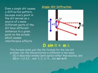
Single Slit Diffraction. Even a single slit causes a diffraction pattern, because every point in the slit serves as a source of a wave. Different parts of the slit have different distances to a given point on the screen, which causes interference effects. D sin q = m l.

D sin q = m l
E N D
Presentation Transcript
Single Slit Diffraction Even a single slit causes a diffraction pattern, because every point in the slit serves as a source of a wave. Different parts of the slit have different distances to a given point on the screen, which causes interference effects. D sinq= ml This formula looks just like the formula for the two-slit problem, but the interpretation is different in two ways: (1) it describes minima (dark spots) rather than maxima; and (2) m = 1,2,3,4,... and -1,-2,-3,-4,... but not m=0.
Remember that rays move perpendicular to the wave front! • Rays that pass straight through are all in phase and create a • central bright spot.
a. Rays that pass at an angle such that the ray from the top of the slit travels exactly one wavelength farther than the ray from the bottom edge, has a ray traveling from the center that is ½ the wavelength from the bottom slit. b. These rays will be out of phase and create destructive interference. c. In fact, each ray passing through the lower half of the slit will cancel it’s corresponding ray in the upper half of the slit. d. Because the rays destructively interfere in pairs, light intensity on the screen at this angle will be zero. e.l = Dsinq
If the top ray differ from the bottom ray by 3/2 l the rays • from the bottom third of the slit will cancel in pairs with the • middle third because they will be ½ l out of phase. • b. Light from the top third of the slit will create a not-so-bright spot
a. What will happen if the top ray differs by twice the wavelength?
a. Notice that the minima occur at D sinq = ml • Where m = 1,2,3,…, but not “0” • Smaller intensity maxima are found between these “m” values. • Note that the minima for a diffraction looks similar to the maxima • for double slit interference. • e. Note that D = single slit width and d = distance between two slits.
The single-slit diffraction pattern has a central maximum that covers the region between the m=1 dark spots. The first secondary maximum appears somewhere between the m=1 and m=2 minima (near but not exactly half way between them). The secondary maximum has a weaker intensity than the central maximum. The subsequent maxima are still weaker.
Diffraction Grating Gratings containing 10,000 lines per cm are common. • Solving problems involving diffraction grating is much like those • in Young’s double slit experiment. • Light rays pass through each slit and interfere constructively • to produce a bright line at the center of the screen. • b. We see that Dl = ml, where m is an integer. • c. If d is the distance between the slits, the Dl = d sinq and • sinq = ml /d • d. This is the same equation as for the double slit situation, but • there are differences!
The bright maxima are much sharper and narrower for • multiple slit patterns than a double slit pattern. • b. Because there is much destructive interference, the maxima • are very narrow. • c. The more lines there are in a grating the sharper and brighter • the lines making gratings an excellent means to measure • wavelengths.
Thin-film interference Constructive and destructive interference of light waves is also the reason why thin films, such as soap bubbles, show colorful patterns. This is known as thin-film interference, because it is the interference of light waves reflecting off the top surface of a film with the waves reflecting from the bottom surface.
White light is separated into colors as it reflects from the two surfaces of a thin film. Where the two reflections interfere constructively, they produce a band of color. Where they cancel each other, that color is subtracted from the spectrum.
To get constructive interference, the two reflected waves have to be shifted by an integer multiple of wavelengths
This must account for any phase shift introduced by a reflection off a higher-n material, as well as for the extra distance traveled by the wave traveling down and back through the film. With the oil film example, constructive interference will occur if the film thickness is 1/4 wavelength, 3/4 wavelength, 5/4, etc
The cancellation (destructive interference) of reflected light waves is utilized to make non-reflective coatings.
The alternating bands of light and dark on this soap film are actually bands of color, produced by the reflection and interference of light waves. The colors depend upon the film's thickness. The film shown here is thinnest at the top, becoming thicker toward the bottom. As the film's thickness changes, the colors also change, forming regular bands.
Coatings are commonly found on some camera lenses or binocular lenses, and often have a bluish tint. The coating is put over glass, and the coating material generally has an index of refraction less than that of glass. In that case, then, both reflected waves have a 180° phase shift, and a film thickness of 1/4 wavelength (in the film) would produce a net shift of 1/2 wavelength, resulting in cancellation.
the yellow arrow plane keeps jumping to a different angle, even though the ray direction remains the same.
Notice that no matter how the yellow arrow twists, the electric forces are always perpendicular to the ray direction. In unpolarized light the twist of the yellow arrow plane keeps changing randomly.
the electric forces in one yellow plane of polarization are completely equivalent to the electric forces in a vertical yellow plane PLUS the forces in a horizontal yellow plane, just as below. This is called "breaking the light up into horizontal and vertical components".
In order to polarize light, you need to pass it through some kind of filter. A good example of this is a Polaroid filter. This kind of filter is made up of parallel strands of long molecules. Let's think of a lens where these strands are horizontal. The energy of the horizontal components of light is absorbed by the strands, so this part cannot pass through. The vertical components can pass through, however, because the horizontal strands cannot absorb their energy.
The more filters you use, the more you can twist the light without it fading. You can vary the intensity of the light by the amount you twist it and by the number of polarizing filters that you pass it through.
http://theory.uwinnipeg.ca/users/gabor/foundations/interfer/slide14.htmlhttp://theory.uwinnipeg.ca/users/gabor/foundations/interfer/slide14.html http://www.exploratorium.edu/ronh/bubbles/bubble_colors.html http://www.colorado.edu/physics/2000/polarization/polarizationI.html
http://hyperphysics.phy-astr.gsu.edu/hbase/phyopt/grating.htmlhttp://hyperphysics.phy-astr.gsu.edu/hbase/phyopt/grating.html http://www.3dglassesonline.com/how-do-3d-glasses-work/ http://physics.usc.edu/~bars/100/Fall2001/lecture22.htm