Download
1 / 19
190 likes | 229 Vues
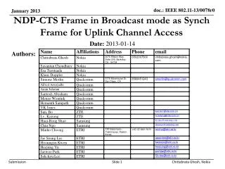
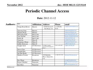
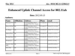
Uplink Channel Access General Procedure. Authors:. Date: 2012-07-12. Authors:. Authors:. Introduction. 11ah use case includes a large outdoor network For an outdoor smart grid network, the number of STAs can be 2007+ TIM element may cover few hundreds to few thousands STAs

E N D
Uplink Channel Access General Procedure Authors: Date: 2012-07-12 YonghoSeok, LG Electronics
Authors: Yongho Seok, LG Electronics
Introduction • 11ah use case includes a large outdoor network • For an outdoor smart grid network, the number of STAs can be 2007+ • TIM element may cover few hundreds to few thousands STAs • Bits set to one in the TIM element may trigger too many PS-Poll/trigger frame transmissions from the STAs within a short period of time • Many stations at the edge of the coverage area could be hidden to each other for uplink transmissions Yongho Seok, LG Electronics
TIM Triggered Hidden Node Problem • Too many bits set in the TIM element may trigger too many PS-Poll/trigger frame transmissions right after the beacon frame within a short period of time • Increase collisions between the hidden nodes TIM (n bits set to 1) Beacon interval STA1 PS-Poll/trigger frame STA2 … STAn n transmissions within a short period of time AP STA2’s transmission range STA1’s transmission range STA1 STA2 Yongho Seok, LG Electronics
TIM Triggered Hidden Node Problem • In order to solve TIM Triggered Hidden Node Problem • One of solutions is either to spread out the uplink transmissions (PS-Poll/Data) over a long period of time or to delay the contention process for sending its PS-poll. • Both solutions have a similarity about delaying or spreading the uplink transmission • Alternative way is that PS-Poll and Data Transmission are separated to different time windows. • Only STAs covered by the AID segment are allowed to access channel within a restricted access window (RAW) DTIM-1 TIM-1.1 TIM-1.2 TIM-1.3 RAW RAW RAW RAW Yongho Seok, LG Electronics
TXOP Rule • Although the hidden node problem can be significantly mitigated by spreading the uplink transmission over a long period of time, the hidden node problem still exists if STA does not wait until a frame sequence is detected by which it can correctly set its NAV, or until a period of time equal to the ProbeDelay has transpired. • The power consumption for the medium synchronization is significant. • One of solutions is to define time slots within the Beacon Interval, where TXOP or transmission within a TXOP shall not extend across a slot boundary Beacon Interval A D P A Collision by Hidden Nodes P * P: Poll, D: DATA, A: ACK Yongho Seok, LG Electronics
Uplink Channel Access Protocol • General Procedure • A Restricted Access Window (RAW) is divided in time slots. • STA wakes up at TBTT and it listens to a Beacon frame that indicates the slot duration for each Restricted Access Window (RAW). • Slot duration for each RAW may be different • STA determines its channel access slot assigned by AP. • STA may sleep before its channel access slot. • STA shall start to access the channel at the slot boundary of its channel access slot based on EDCA. • AP indicates whether the following TXOP rule is applied in each RAW: • A TXOP or transmission within a TXOP shall not extend across a slot boundary • If the above TXOP rule is applied, the STA does not wait for ProbeDelay when waking up at the slot boundary. Beacon Interval Slot Boundary Slot Boundary Slot Boundary Slot Boundary Slot Boundary Slot Boundary Slot duration Restricted Access Window (RAW) Yongho Seok, LG Electronics
Uplink Channel Access Protocol • RAWs with different slot durations • If the TXOP rule is applied, a frame exchange sequence (an initial frame and a response frame) in a restricted access window shall be limited to a Slot Duration • RAW1 can be a potentially protected poll interval. • RAW2 can be a potentially data delivery interval. Beacon Interval Slot duration = Ts1 Slot duration = Ts2 > Ts1 P A P A D A D A RAW1 RAW2 * P: PS-Poll/Trigger frame D: DATA, A: ACK Yongho Seok, LG Electronics
Uplink Channel Access Example • RAW1 (=Protected Poll Interval) • GrPS IE of RAW1 indicates that only the STAs that meet the below conditions can access RAW1 • The RAW is allowed only to the STA’s with AID bit = 1 in the TIM IE • Slot duration = Ts1 ,where Ts1 is set to (PS-Poll + SIFS +ACK) or (Null Data + SIFS +ACK) • TXOP cross slot boundary = not allowed • This effectively makes RAW1 to be used for only PS-Poll or Null-Data trigger frames • RAW2 (=Data Delivery Interval) • GrPS IE of RAW2 indicates that only the STAs that meet the below conditions can access RAW2 • The RAW is allowed only to the STA’s with AID bit = 1 in the TIM IE • Slot duration = Ts2 ,where Ts2 is set to be large enough to transmit (Data + SIFS +ACK) • TXOP cross slot boundary = not allowed • This effectively makes RAW2 to be used for the AP to transmit Data frames to the STAs with their AID bits set to 1 • If there is time left in a time slot, a STA can transmit data to the AP as long as it doesn’t cross the slot boundary TIM bitmap (4 AID bits are set to 1) 1 0 1 0 0 1 0 0 1 0 Beacon Interval Slot duration = Ts1 Slot duration = Ts2 > Ts1 • P: Poll • D: Data (APSTA) • D: Data (STAAP) • A: ACK A A P P P P D D D D D AP STAj AP STAi STAj AP RAW1 RAW2 Yongho Seok, LG Electronics
Downlink Buffered BU Delivery Procedure • AP may indicate to a paged STA a channel access slot after which the STA is allowed to contend • Preferred an implicit indication, based on TIM, so that the Beacon is not overloaded • Additional information [TBD] for determining a RAW duration may be needed in (short) Beacon • After receiving TIM, STA transmits the PS-Poll/Trigger frames to a AP not earlier than the slot boundary of its channel access slot based on EDCA • AP may indicate to a paged STA, that it will be sending traffic to a STA not earlier than a given downlink BU delivery slot. • Indication of the downlink BU delivery slot should not overload the beacon • New management frame indicates the downlink BU delivery slot per each STA after all PS-Poll/Trigger frame transmission completed. • AP may protect the PS-Poll/Trigger frames by setting the NAV • The paged STAs can ignore the NAV set by the AP. If NAV is set, then only paged STAs can send PS-Poll/Trigger frames during the RAW Yongho Seok, LG Electronics
Downlink Buffered BU Delivery Example • After all awakened STAs exchanged PS-Poll/Trigger and ACK frames, the AP broadcasts a slot assignment frame which includes estimated downlink buffered BU transmission time for STAs. • Details on the new management frame format is TBD. • P: Poll • D: Data (APSTA) • D: Data (STAAP) • A: ACK • B : Broadcast TIM bitmap (4 AID bits out of 10 bits are set to 1) 1 0 1 0 0 1 0 0 1 0 AID: 1 2 3 4 5 6 7 8 9 10 Beacon Interval AID1 AID3 AID9 AID1 AID3 AID9 B D D P P P D RAW1 (paged STAs only) RAW2 (paged STAs only) Yongho Seok, LG Electronics
Uplink Frame Delivery Procedure • AP may allow a STA/group-of-STA to transmit an uplink frame anytime. • AP may assign to each STA/group-of-STA a channel access slot at which the STA is allowed to contend through a Beacon frame • STA wakes up at TBTT and it listens to a Beacon frame • STA determines its channel access slot through the Beacon frame • STA starts to access the channel not earlier than the slot boundary of its channel access slot; access is based on EDCA. • When requested by a STA, AP may assign to the STA a channel access slot at which the STA is allowed to contend, at association or later through a management frame exchange • STA starts to access the channel not earlier than its slot boundary of its channel access slot; access is based on EDCA. Yongho Seok, LG Electronics
Uplink Frame Delivery Example • At association (or later through a management exchange) AP indicates to a STA a time interval at which the STA is allowed to contend • Time may be defined as a periodic interval • Offset may be indicated with respect to a given beacon time • Signaling ‘similar’ to FMS • Example1 • - Example2 Beacon Beacon STA4, 5 STA4, 5 STA2 STA3 STA2 STA3 Beacon Beacon STA1,2,3,4,5 STA6,7,8,9,10 Yongho Seok, LG Electronics
Conclusion • 11ah use case includes a large outdoor network • Many stations at the edge of the coverage area could be hidden to each other • Bits set in the TIM element may trigger collisions between the hidden nodes • When hidden nodes are present in the network, spreading the uplink channel accesses over a much longer period of time significantly reduces the collisions • Some simulation results are shown in [1]. • In this joint contribution, we propose a general procedure for an uplink channel access • Detail about how the STA determines its channel access slot is TBD. Yongho Seok, LG Electronics
References [1] 802.11-12/0606r0, Uplink Channel Access [2] 802.11-12/0329r0, Group Synchronized DCF [3] 802.11-12/0823r0, Target Wake Time [4] 802.11-12/0840r0, AP assisted medium synchronization Yongho Seok, LG Electronics
Straw Poll 1 • Do you support to include the uplink channel access protocol of slide 8 in the TGah spec framework document? Yongho Seok, LG Electronics
Straw Poll 2 • Do you support to include the downlink buffered BU delivery procedure of slide 11 in the TGah spec framework document? Yongho Seok, LG Electronics
Straw Poll 3 • Do you support to include the uplink frame delivery procedure of slide 13 in the TGah spec framework document? Yongho Seok, LG Electronics