ECE 291
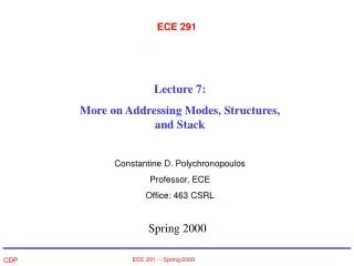
ECE 291. Lecture 8: Real & Protected Mode Paging and Virtual Memory Constantine D. Polychronopoulos Professor, ECE Office: 463 CSRL. Spring 2000. Segment Offset Special Purpose CS IP Instruction address SS SP or BP Stack address DS BX, DI, SI, Data address

ECE 291
E N D
Presentation Transcript
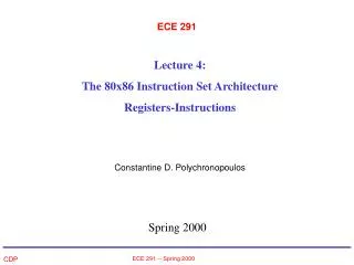
ECE 291 Lecture 8: Real & Protected Mode Paging and Virtual Memory Constantine D. Polychronopoulos Professor, ECE Office: 463 CSRL Spring 2000 ECE 291 -- Spring 2000
Segment Offset Special Purpose CS IP Instruction address SS SP or BP Stack address DS BX, DI, SI, Data address an 8- or 16-bit number ES DI for string ops String destination address Real Mode Addressing - Up to 1Mb of addressable memory. Address is always computed by <segment reg: displacement> where each of the two can be 16-bits. - Segment register is always extended with a 0H at the right end. - Hence: up to 20 bits of address => 1Mb of memory - Segments (or paragraphs) are always 64Kb 16-bit Default Segment + Offset address combinations: ECE 291 -- Spring 2000
Segment Offset Special Purpose CS EIP Instruction address SS ESP or EBP Stack address DS EBX, EDI, ESI, Data address EAX, ECX, EDX, an 8- or 32-bit number ES DI for string ops String destination address FS No default General address GS No default General address Real Mode 32-bit Default Segment + Offset address combinations: =>In 386-Pentium III, never place a number > FFFFH in an offset register I when operating in real mode ECE 291 -- Spring 2000
Real Mode (cont.) • Up to 4 64Kb-segments for < x286 - up to 6 segments for >= x386 • Program can use any arbitrary number of segments but only 4/6 can be addresses simultaneously at any given time • Note: If a user segment does not use all 64Kb of memory segment regs can be initialized so that segments can overlap - it’s your responsibility to assure the overlap does not create unwanted side-effects! • DOS or any OS is responsible for linking and loading a user program, figuring out the code-data-stack segments, dynamic data area, and initializing the corresponding segment registers. ECE 291 -- Spring 2000
Data Stack Memory FFFFF Code Stack Data 0A47F 0A27F 0A0EF Code DS CS SS 0A480 090F 0A28 0A0F 0908F 090F0 0A280 0A0F0 OS & drivers 00000 Example of Overlapping Segments Conceptual overlap ECE 291 -- Spring 2000
Real Mode (cont.) • Segment registers allow programs to be written using only offset address and still be relocated anywhere in memory: all we need to do to move a code/data/stack segment is to change the corresponding segment register - all offset addresses remain same. • Relocation of code and data is very important for: • up/downward compatibility • write programs without concerned about the memory size of the particular machine they execute on • moving programs around in memory and allowing multiple programs to run simultaneously • Segment regs are used to address real memory addresses in Real Mode only. • The result is similar to Virtual Memory (in ECE 312) ECE 291 -- Spring 2000
Protected Mode: >= x386 • In protected mode (where memory is much larger) we have yet another indirection: Segments are still 64K large but now segment regs no longer point to memory directly - they point to descriptors which then point to the beginning of a segment in memory. • The drawback is a more expensive address translation mechanism • But the benefit is that we can relocate any segment anywhere in 4Gb space, customize access rights to each segment, share segments with different programs/applications, etc. • NOTE: Protected mode does NOT require any change in the application either (unless you customize protection rights) since the indirection is handled automatically by the linker/loader. ECE 291 -- Spring 2000
Protected Mode: General • In PM, segment point now to descriptor tables - which then give us the starting address of the segment • Each DT contains 8K (8,192) descriptors where each descriptor is an 8-byte quantity that describes a memory segment. There are two DT: • Global (or System) descriptor • Local (or application) descriptor • Therefore we have up to 16K (2 x 8,192) memory segments that can be addressed in PM by each application. • The two DTs reside in memory and take up a max of 64Kb of memory (8b x 8K). ECE 291 -- Spring 2000
G D 0 A V 80286 Descriptor 386-Pentium III Descriptor Base B31-B24 Limit L19-L16 00000000 00000000 Base(B23-B16) Access rights Base(B23-B16) Access rights Base (B15-B0) Base (B15-B0) Limit (L15-L0) Limit (L15-L0) Format of Descriptors in PM: - Each descriptor is 8 bytes long - Base is the base address of segment in memory: in x286 it’s 24-bits but in x386+ it can be 32-bits. (Smallest mem. granularity is 4Kb so in x386+, least significant 12 bits can be ignored in Base => 24+21=32 bit addresses) - Limit is the last offset in segment: i.e. variable size segments in PM. In x286 limit is 16-bits bit in x386+ it is 20bits. e.g. - x286: Segment begins at F00000H and ends at F000FFH => it has base F00000H and has a limit of 00FFH. e.g. - x386: same segment would begin at 00F00000H and will have a limit of 000FFH (20 bits) ECE 291 -- Spring 2000
G D 0 A V 386-Pentium III Descriptor Base B31-B24 Limit L19-L16 Base(B23-B16) Access rights Base (B15-B0) Limit (L15-L0) PM: Descriptor Format G - granularity bit: Specifies the size of segment incremets: - G=0 => Limit specifies a segment limit of 00000H to FFFFFH - G=1 => Limit specifies a segment limit of 00000XXXH to FFFFFXXXH (G=1 allows a segment length of 4Kb-4Gb in increments of 4Kb) Example 1: Base =Start= 10000000H G=0 End=Base+Limit=10000000H + 001FFH = 100001FFH Example 2: Base =Start= 10000000H G=1 End=Base+Limit=10000000H + 001FFXXXH = 101FFFFFH The extension XXX can take any value from 000 to FFF ECE 291 -- Spring 2000
G D 0 A V 386-Pentium III Descriptor Base B31-B24 Limit L19-L16 Base(B23-B16) Access rights Base (B15-B0) Limit (L15-L0) Segment Register in PM: RPL=requested privilege level (00-highest, 11-lowest) RPL TI Descriptor Selector TI=0 => Global descriptor table TI=1 => Local descriptor table Selects one of 8,192 descriptors in global or local description tables PM: Descriptor Format (cont.) AV - bit: Specifies whether the segment is available or not. D-bit: Specifies how memory is accessed in RM or PM - D=0 => Default: 16-bit instructions, offsets and registers - D=1 => Default: 32-bit instructions, offsets and registers NOTE: The default of register size and offset size can be overridden in both 16- and 32-bit instruction modes. Access Rights byte: Specifies access rights, access violation actions, direction of growth (for data segments) - e.g., shared code segments ECE 291 -- Spring 2000
How do we access DT in PM? • In PM registers contain offsets into the DT (or selectors), not segment addresses (which are contained in the descriptors) • The processor “knows” where to find the DT: a special register, GDTR (invisible) keeps the base address of the DT. • Each time a segment register changes (indicating that a new segment is to be accessed => a DT access is needed) the following actions take place: • GDTR + segment reg => address in memory from where to get Descriptor • Descriptor (Base, Limit, Access) is fetched in an invisible register in the processor (descriptor cache) where it’s kept so that DT is not accessed with each memory access (too expensive) • When a segment register is reloaded the corresponding DT cache entry is invalidated ECE 291 -- Spring 2000
System (Invisible) Registers • Besides a GDTR and a LDTR there are 10 descriptor caches (i.e. registers that cache DT entries) • Also, there is a task register, TR, which holds a selector of a descriptor that defines a task (i.e. a procedure, or application). The TR allows a context (task) switch in only 17μs. • TR allows switching from one application program to another in a short period of time. This is also known as multiprogramming, multitasking, or time-sharing. • TR points to a descriptor in the global descriptor table. ECE 291 -- Spring 2000
PAGING • Paging: Maps a virtual to a physical address: • Linear (virtual) address ==> physical address • Paging also extends the “size” of memory beyond that of physical memory (DRAM). The principle works by fetching and keeping in memory only those segments that are currently accessed to make progress in the execution. All other code/data may be in disk (linear addresses that are not currently present in physical memory). • Why paging? Because segmentation is not enough to allow multiple applications to reside in memory at the same time and thus execute “together” - the reason is that we need separate segment registers for each application but we also need to make sure that different application segments map to different physical memory segments. This, would severely limit the # of apps that can run together as well as the range of memory they could address: no longer relocatable! • Paging solves all of the above problems! ECE 291 -- Spring 2000
Paging (cont.) • Memory Management Unit MMU (or memory paging unit - MPG) translates linear to physical addresses. • Paging is controlled by the (invisible) control registers that keep the location of the mapping tables known as the page table directory (PTD) and the page map tables (PMT). The address translation process then follows the steps: • Use a control register to get the base of PTD • Use MSBs of the linear address as an offset into PTD to get entry • Entry gives the base of the PMT for this application. Add to it the next MSBs of the linear address to get entry of PMT. • This entry gives the location in physical memory of the base of the segment we want to access. Add to it the LSBs of the linear address to form the byte address of data or instruction to acceess. • Paging works with real and with protected mode ECE 291 -- Spring 2000
Paging - Control Registers • Control registers: CR0-CR3 (and in Pentium CR4) are 32b regs. Bit 0 (MSB) of CR0 is used to set paging on/off. If CR0(0)=0 the linear address is also the physical address. Otherwise, paging is enabled. • CR3 has the page directory page address - there is only one page directory in the entire system with up to 1,024, 32-bit entries. • Each entry in the page directory points to a page table. Each page table contains up to 1,024, 32-bit entries, each pointing to a physical memory page (segment). • Thus, we have up to 220 x 4bytes = 4Mb of physical memory reserved only for the PMT -- way too much! • Usually, a PMT is needed for each active application, and in practice there are only a few PMTs. However, the 4Kb space for the page directory must be reserved and available. ECE 291 -- Spring 2000
0 0 6 11 12 22 31 31 21 12 Linear (virtual) address: Address Directory Offset Control bits Page Table CR3 (Page directory base) PMT entry - points to base of memory (page) segment: Page Table base address This is what used to be the Segment Register in RM 32-bit Physical Address Paging: Address Translation ECE 291 -- Spring 2000
Paging Examples - Range of linear addresses that map to 1st entry of page directory: Answer:00000000H - 003FFFFFH (or 00000000000…. - 00000000001111….) - What range of memory can be mapped for each directory entry? Answer: Each entry is base of a 1K-entry page table. Each of these entries points to base of a 4Kbyte of memory => 1K x 4Kb = 4Mb - Accessing memory and performing all these operations for each linear address generated by a program would be prohibitively expensive! Solution: Translation Lookaside Buffer (TLB) contains the 32 most recent <linear-to-physical> translations. When an new addr. references one of the 32 most recent 4Kb segments, the mapping is available in the TLB and we need not compute it. This speeds up computation significantly. Also, due to temporal/spatial locality TLB hits account for the great majority of translations!! ECE 291 -- Spring 2000
Recall Instruction Format: OPCODE: D - Direction of data transfers: - D = 0: data transfers from R/M field to Register - D = 0: data transfers TO the Register from R/M field in next byte W - Data size: - W=0: data size is a byte - W=1: data size is a word/double word | | | | | | D|W ECE 291 -- Spring 2000
MOD Format 00 No displacement 01 8-bit sign-extended disp. 10 16-bit displacement 11 R/M is a register MOD REG R/M 2 3 3 MOD: Selecting Addressing Mode - MOD field: 1 byte that specifies the addressing mode + enables/disables displacement. - Only when MOD=11 => R/M field is a register specifier ECE 291 -- Spring 2000
MOD REG R/M 2 3 3 REG: Specifying the Register inRegister Assignment Code W=0: Byte W=1: word or doubleword 000 AL AX or EAX 001 CL CX or ECX 010 DL DX or EDX 011 BL BX or EBX 100 AH SP or ESP 101 CH BP or EBP 110 DH SI or ESI 111 BH DI or EDI ECE 291 -- Spring 2000
Code Address Function 000 DS: [BX+SI] 001 DS: [BX+DI] 010 SS: [BP+SI] 011 SS: [BP+DI] 100 DS: [SI] 101 DS: [DI] 110 SS: [BP] 111 DS: [BX] R/M Field: Selecting Addressing Mode -If MOD is 00, 01, 10, then R/M does not specify a register operand, but memory addressing mode: Examples: 1. If MOD=00 and R/M=101: addressing mode is [DI] 2. If MOD=01 and R/M=101 addressing mode is [DI +disp] 3. If MOD=10 and R/M=101 addressing mode is disp1[DI+disp2] ECE 291 -- Spring 2000
Example 1 The instruction 10001011 11110010 (or 8BF2H) has: OPCODE=100010 indicates a MOV D=1 indicates that data flows into register W=1 indicates word or doubleword data MOD=11 indicates that the R/M field also specifies a register REG=110 indicates SI and R/M=010 indicates DX Therefore: MOV SI, DX ECE 291 -- Spring 2000
Example 2 The instruction 10001010 00010101 (or 8BF2H) has: OPCODE=100010 indicates a MOV D=1 indicates that data flows into register specified in REG W=0 indicates byte MOD=00 no displacement REG=010 indicates DL R/M=101 indicates addressing mode [DI] Therefore: MOV DL, [DI] ECE 291 -- Spring 2000