Download
1 / 24
240 likes | 371 Vues
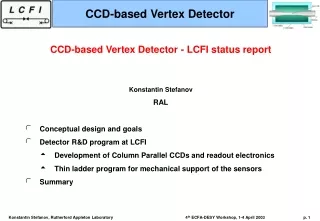
A CCD-based vertex detector. Status report from the LCFI collaboration Konstantin Stefanov RAL Overview of the LCFI programme Conceptual design of the vertex detector for the future LC Detector R&D program at LCFI Development of very fast CCDs and readout electronics

E N D
A CCD-based vertex detector Status report from the LCFI collaboration Konstantin Stefanov RAL • Overview of the LCFI programme • Conceptual design of the vertex detector for the future LC • Detector R&D program at LCFI • Development of very fast CCDs and readout electronics • Experimental studies on a commercial high speed CCD • Thin ladder programme for mechanical support of the sensors • Summary
LCFI Overview Work in two directions: Simulation of CCD-based vertex detector performance using physics processes at the LC (Chris Damerell’s talk) Detector R&D: development of fast CCDs for the vertex detector and their support structure Physics studies are continuing, but we know that: • Many particles in jets with low momentum ( 1 GeV/c) even at high collision energy, multiple scattering still dominant; • Very efficient and pure b and c tagging needed; • Vertex charge measurement important.
Detector Parameters Impact parameter resolution: , [m] Thin detector (< 0.1% X0) for low error from multiple scattering Close to the interaction point for reduced extrapolation error Readout time: 8 ms for NLC/JLC (read between trains) 50 s for TESLA (read the inner CCD layer 20 times during the train) Two track separation 40 m, small pixel size 20 m 20 m; Large polar angle coverage; Stand-alone tracking: 4 or 5 layers of sensors; Radiation hard. Pushing the technology hard…
Conceptual design 5 layers at radii 15, 26 37, 48 and 60 mm; Gas cooled; Low mass, high precision mechanics; Encased in a low mass foam cryostat; Minimum number of external connections (power + few optical fibres).
CCD development Large area, high speed CCD – follows the ideas of the SLD VXD3 design Pixel size: 20 m square Inner layer CCDs: 10013 mm2 Outer layers: 2 CCDs with size 12522 mm2 120 CCDs, 799106 pixels total Readout time 8 ms in principle sufficient for NLC/JLC For TESLA: 50 s readout time for inner layer CCDs: 50 Mpix/s from EACH CCD column Future LC requires different concept for fast readout – Column Parallel CCD (CPCCD) Natural and elegant development of CCD technology
Column parallel CCD M N N+1 “Classic CCD” Readout time NM/Fout Column Parallel CCD Readout time = (N+1)/Fout Serial register is omitted Maximum possible speed from a CCD (tens of Gpix/s) Image section (high capacitance) is clocked at high frequency Each column has its own amplifier and ADC – requires readout chip
CCD ladder end List of issues to be solved: • Bump bonding assembly between thinned CPCCD and readout chip • Driving the CPCCD with high frequency low voltage clocks; • Driver design; • Low inductance connections and layout; • Clock and digital feedthrough; • Cooling the ladder end.
Readout chip CCD bump-bonded to custom CMOS readout chip with: Amplifier and ADC per column Correlated Double Sampling for low noise Gain equalisation between columns Pixel threshold Variable size cluster finding algorithm Data sparsification Memory and I/O interface
Column Parallel CCD Important aspects of CPCCD: Quality of 50 MHz clocks over the entire device (area = 13 cm2): • All clock paths have to be studied and optimised Power dissipation: • Pulsed power if necessary • Low clock amplitudes • Large capacitive load (normally 2-3nF/cm2) Feedthrough effects: • 2-phase drive with sine clocks – natural choice because of symmetry and low harmonics • Ground currents and capacitive feedthrough largely cancel Most of these issues are being studied by simulation
Device simulations Charge packet in a 2-phase CCD • Using ISE-TCAD software and SPICE models • 2D models for: • potential profiles; • low voltage charge transfer • feedthrough studies • 3-D models being used as well • SPICE simulations of clock propagation
Device simulations Extensive simulation work done at RAL; 2D model for standard 2 phase CCD developed; Electric fields and charge transfer times can be calculated; In simulation 50 MHz transfer achieved with 1.5 Vpp clocks – to be compared with real device; Clock propagation over the CCD area largely understood; Will use polysilicon gates (30 /sq) covered with aluminium (0.05 /sq) for high speed.
Hybrid assembly CPCCD-CMOS Standard 2-phase implant Field-enhanced 2-phase implant (high speed) Metallised gates (high speed) Metallised gates (high speed) 2-stage source followers Source followers Source followers Direct Direct Readout ASIC Readout ASIC To pre-amps Features in our first CPCCD: • 2 different charge transfer regions; • 3 types of output circuitry; • Independent CPCCD and readout chip testing possible: • Without bump bonding - use wire bonds to readout chip • Without readout chip - use external wire bonded electronics • Designed to work in (almost) any case.
CPCCD design • Designed by E2V (former Marconi Applied Technologies, EEV); • Fruitful long-term collaboration: the same people designed the CCDs for VXD2 and VXD3; • In production, to be delivered November 2002 • Several variants: • For standalone testing and for bump bonding; • With/without gate and bus line shield metallisation; • Variable doping, gate thickness • First step in a 5 or 6 stage R&D programme.
Test readout chip design A comparator using Charge Transfer Amplifier, repeated 31 times per ADC Readout chip designed by the Microelectronics Group at RAL; 0.25 m CMOS process; Charge Transfer Amplifiers (CTA) in each ADC comparator; Scalable and designed to work at 50 MHz. CPR-0 : Small chip (2 mm 6 mm) for tests of the flash ADC and voltage amplifiers, already manufactured and delivered, currently being tested; CPR-1 : Contains amplifiers, 250 5-bit ADCs and FIFO memory in 20 m pitch.
Test readout chip design Wire/bump bond pads Charge Amplifiers Voltage Amplifiers 250 5-bit flash ADCs FIFO Bump bond pads In CPR-1: • Voltage amplifiers – for source follower outputs from the CPCCD • Charge amplifiers – for the direct connections to the CPCCD output nodes • Amplifier gain in both cases: 100 mV for 2000 e- signal • Noise below 100 e- RMS (simulated) Direct connection and charge amplifier have many advantages: • Eliminate source followers in the CCD • Reduce power 5 times to 1 mW/channel • Programmable decay time constant (baseline restoration) ADC full range: 100 mV, AC coupled, Correlated Double Sampling built-in (CTA does it)
Tests of high-speed CCDs E2V CCD58 3-phase, frame transfer CCD 2.1 million pixels in 2 sections 12 m square pixels High responsivity: 4 V/electron 2 outputs (3-stage source followers) Bandwidth 60 MHz Test bench for high-speed operation with MIP-like signals
Tests of high-speed CCDs CCD58 55Fe X-ray spectrum at 50 Mpix/s MIP-like signal (5.9 keV X-rays generate 1620 electrons); Low noise 50 electrons at 50 MHz clocks; CCD58 is designed to work with large signals at 10 Vpp clocks; No performance deterioration down to 5 Vpp clocks; Still good even at 3 Vpp clocks.
Tests of high-speed CCDs Low drive voltage tests at 50 Mpix/s: Actual clock traces and 55Fe X-ray spectrum Radiation damage effects: Backgrounds: 50 krad/year (e+e- pairs) 109 neutrons/cm2/y (large uncertainty) Radiation damage effects on CCD58 being studied; Radiation-induced CTI should improve a lot at speeds > 5-10 Mpix/s – to be verified; Flexible clocking of CCD58 from 0.625 MHz to 50 MHz – should be able to get good results;
Thin ladder R&D A program to design a CCD support structure with the following properties: • Very low mass (< 0.4% X0 – SLD VXD3) • Repeatability of the shape to few microns when temperature cycled down to –100 C; • Minimum metastability or hysteresis effects; • Compatible with bump bonding; • Overall assembly sufficiently robust for safe handling with appropriate jigs; • Structure must allow use of gas cooling.
Thin ladder R&D Compression CCD 1 CCD 2 Tension V and flat sliding joint Ladder block Annulus block Silicon Ceramic Three options: • Unsupported CCDs – thinned to 50 m and held under tension • Semi-supported CCDs – thinned to 20 m and attached to thin (and not rigid) support, held under tension; • Fully-supported CCDs – thinned to 20 m and bonded to 3D rigid substrate (e.g. Be) The first version has been studied experimentally: sagitta stability vs. tension: better than 2 m at tension > 2N
Unsupported silicon Adhesive pulls silicon down Silicon Adhesive Ceramics Butt joint Silicon Adhesive Several problems: Large differential thermal contractions at the CCD surface (oxides, passivation, metals) – cause lateral curling Handling: testing, bump-bonding, etc. very difficult Semi-supported option currently under study
Semi-supported silicon • CCD (20 μm thin) bonded with adhesive pads to 250 μm Be substrate • On cooling adhesive contracts more than Be pulls Si down on to Be surface • Layer thickness 0.12% X0 • 1 mm diameter adhesive columns inside 2 mm diameter wells 200 μm deep in Be substrate 6 m 3 m Extensively simulated using ANSYS, a model will be made soon • CCD surface may become dimpled – under study • May need very fine pitch of adhesive pad matrix difficult assembly procedure, weakened substrate, complex non-uniform material profile…
Semi-supported structures Carbon fibre support Aerogel support Carbon fibre: CTE is tunable, layers can have optimal orientation and fibre diameter, difficult to simulate Aerogel support: chemically bonds to Si, aerogel in compression Many other ideas: CVD diamond, vacuum retention, etc…
Summary • Detector R&D work at the LCFI collaboration is focused on: • Development of very fast column parallel CCD and its readout chip; • Study the performance of commercial CCDs with MIP-like signals at high speeds and radiation damage effects; • Precision mechanical support of thinned CCDs. • CCD-based vertex detector for the future LC is challenging, but looks possible; • Major step forward from SLD VXD3, significant customisation required; • Many technological problems have to be solved; • Have to work hard, R&D is extensive and complex; • Different versions of the CPCCD likely to find warm welcome in science and technology. More information is available from LCFI’s web page: http://hep.ph.liv.ac.uk/~green/lcfi/home.html