Download
1 / 32
320 likes | 339 Vues
This paper discusses the development of Advance Microwave Sounding Unit (AMSU) and Microwave Humidity Sounder (MHS) Climate Data Records (CDRs) for hydrological applications. It focuses on the geolocation correction of AMSU and MHS data and the potential use of these CDRs for climate variability and change analysis.

E N D
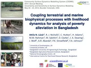
Climate data records from microwave satellite data: a new high quality data source for reanalysis Isaac Moradi1, H. Meng2, R. Ferraro2, C. Devaraj1, W. Yang1 CICS/ESSIC, University of Maryland, College Park NESDIS/STAR, NOAA, College Park
Outlines • Overview of the CDR project • AMSU/MHS products • Geolocation correction (the focus of the talk) • Scan Asymmetry Correction
The Development of AMSU FCDR’s and TCDR’s for Hydrological Applications Definition for CDR (Wiki): According to NRC [National Research Council 2004. Climate Data Records from Environmental Satellites. Washington D.C.: National Academy Press.I SBN-10: 0-309-09168-3, ISBN 978-0-309-09168-8] "a time series of measurements of sufficient length, consistency, and continuity to determine climate variability and change.“ Goals • Develop Advance Microwave Sounding Unit-A and -B (AMSU-A/-B), and Microwave Humidity Sounder (MHS) FCDR’s for AMSU-A window (23.8, 31.4, 50.3, 89.0 GHz) and all AMSU-B/MHS channels (89, 150/157; 183.3+1, 183.3+3, 183.3+7/190.3 GHz) • Develop TCDR’s for hydrological products: Rain Rate, TPW, CLW, IWP, Snow Cover, SWE
Products • AMSU (MSPPS) hydrological products * In MIRS, all AMSU-A, -B/MHS channels are used in product retrievals
Sample Products Rain Rate Total Precipitable Water Ice Water Path Snow Cover Snow Water Equivalent Cloud Liquid Water
Data, Products, Users • Source Data • NOAA-15,16,17,18,19 L1B data • MetOp-A L1B data • Deliverables • FCDR’s from 2000 – 2010 for all satellites (perhaps to 1998 for NOAA-15) • TCDR’s; same time periods • Current/Expected Users • National: government (NASA, NOAA, NRL); science community • International: IPCC; GEWEX (GPCP); CEOS; GCOS; IPWG • Other – General climate community
Sources of geolocation errors • Human errors • Satellite clock offset • Satellite attitude offset and sensor pointing errors • Satellite attitudes are known as Pitch, Roll and Yaw (in mathematics: Euler • Angles) and are included in the geolocation algorithm by a rotation matrix • 4. Poor spacecraft ephemeris data • The implemented correction • method will take care of all • sources of errors. • The method is just applicable • to the microwave window channels
Difference between NOAA-L1b and new geolocation The Advanced Earth Location Data System (AELDS) failed to calculate GHA Wrong MHS Step Angle
Error in MHS Step Angle MHS Step Angle is 10/9 but was taken as 1.1 until 05-217. The first orbit with correct step angle is SS.MHSX.NN.D05217.S1529.E1714.B0108889.GC
Clock offset for NOAA POES satellites In the original NOAA-L1b data, the clock offset is not taken into account for geolocating NOAA-17 data
Satellite attitudes Roll YAW Pitch Source: Wikipedia
Quantifying the geolocation error • No geolocation error => ΔTB, ascending – descending, is very small (diurnal variation, environmental conditions, limb effect). • Geolocation error => ΔTb is very large along the coast lines because the land TB is much higher than ocean TB • negative alongtrack offset => northern coastlines will have acoldedge, and southerncoastlines will have a warmedge. • negative crosstrack offset =>westerncoastlines will have a coldedge and the easterncoastlines will have awarmedge
Sample difference map Index = number of pixels along the coastlines where ΔTb > threshold
How to tune pitch, roll, and yaw? Pitch = 0, Roll = 0, Yaw = 0 Tune Roll Tune Yaw Tune Pitch Calculate lat/long using SGDP and TLE Step 1 Step 2 Step 3 Correction Required ? Calculate #pixels where ΔTb > threshold Yes Step < 4 Yes No No store lat/lon and LZA
Scan bias characterization method Clear sky AMSU-B/MHS FOV determined by PATMOS-X Over tropical/subtropical oceans ERA-Interim T, q, O3 profiles ERA-Interim SST, U & V AMSU-B/MHS LZA, Scan angle AMSU-B/MHS 1b raw count Ta CRTM Tb Tb Compare collocated Tb’s with same atmospheric condition for each beam position
LowPW:0-2.5, HighPW:4-6, mpvPW:2.5-4 LowWind:0-3, HighWind:7-1, mpvWind: 3-7
CLW and Land Emissivity at 31.4 GHz: Before vs. After Correction
Questions? Isaac Moradi imoradi@umd.edu Reference: Moradi, I, Meng, H., Ferraro, R, Bilanow, S., 2012. Correcting geolocation errors for microwave instruments aboard NOAA satellites. IEEE Trans. Geoscience and Remote Sensing (under review)