Intelligent Transportation Systems (ITS) for Public Transport Vehicles
500 likes | 551 Vues
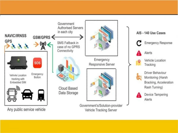
This draft standard outlines requirements for the implementation of Intelligent Transportation Systems (ITS) in public transport vehicles to enhance efficiency, quality, comfort, and safety. It includes guidelines for vehicle location tracking, camera surveillance, and emergency request systems.

Intelligent Transportation Systems (ITS) for Public Transport Vehicles
E N D
Presentation Transcript
DraftAIS-140/DF1/ May2017 FINALIZEDDRAFT AUTOMOTIVE INDUSTRY STANDARD Intelligent Transportation Systems(ITS) - Requirements for Public Transport VehicleOperation ARAI I
DraftAIS-140/DF1/ May2017 CHECK LIST FOR PREPARING AUTOMOTIVE INDUSTRYSTANDARD AIS-140: Intelligent Transportation Systems (ITS) - Requirements for Public Transport Vehicle Operation II
Draft AIS-140/DF/May2017 Status chart of the Standard to be used by the purchaser for updating therecord Generalremarks: III
Draft AIS-140/DF/May2017 INTRODUCTION The Government of India felt the need for a permanent agency to expedite the publication of standards and development of test facilities in parallel when the work on the preparation of the standards is going on, as the development of improved safetycriticalpartscanbeundertakenonlyafterthepublicationofthestandardand commissioning of test facilities. To this end, the erstwhile Ministry of Surface Transport (MoST) has constituted a permanent Automotive Industry Standards Committee (AISC) vide order No. RT-11028/11/97-MVL dated September 15, 1997. The standards prepared by AISC will be approved by the permanent CMVR Technical Standing Committee (CTSC). After approval, the Automotive Research Association of India (ARAI), Pune, being the secretariat of the AIS Committee, will publish this standard. Intelligent Transport Systems (ITS) are globally proven systems to optimize the utilization of existing transport infrastructure and improve transportation systems in terms of efficiency, quality, comfort and safety. Having realized the potential of ITS, Government bodies and other organizations in India are presently working towards implementing various components of ITS across thecountry. The first step taken for creation and implementation of ITS was holding a National Workshop titled “User Requirements for Interactive ITS Architecture”, which was conducted as a collaboration between SIAM and ASRTU on 26th & 27th February 2015. This was primarily focused on ITS in Public Bus Transportation. Nonetheless, the workshop helped to create the outline for “National Intelligent Transport System Architecture and Policy for Public Transport (Bus)”, which was submitted by ASRTU and SIAM to the government In the 44th & 45th CMVR-TSC, Chairman had directed - standardization activities to be initiated on Intelligent Transportation Systems (ITS) - Vehicle Location Tracking, Camera Surveillance System and Emergency Request Button. The committee intended to extend the above user requirements to all public transportation namely – buses, taxis, etc. The current document covers the requirements for Vehicle Location Tracking and Emergency Button. The other ITS components like PIS, CCTV system, Fare collection etc. are deliberated and would be addressed in later phase and could be added as separate parts to the currentdocument.. Based on these directions, the AISC Panel on ITS has prepared this AIS-140 titled, “Intelligent Transportation Systems (ITS) - Requirements for Public Transport VehicleOperation” The panel has also deliberated and identified the necessary elements for an effective implementation of vehicle level ITSsystem. This standard has been prepared by considering inputs received from all stake holders on ITS, mainly- VI
Draft AIS-140/DF/May2017 • Directions of CMVR-TSC • Detailed Specification Document on Vehicle Tracking Devices (dated 4th March 2015, published byMoRTH) • Report of Department of Telecom (Telecom Engineering Centre) Automotive Working Group on M2M enablement in Intelligent Transport System(ITS) • This AIS on ITS, has been provisioned for device level approval; including construction and target vehicle level approval. Device level approval is needed to enable retro-fitment of ITS systems on in-use vehicles. This will ensure ITS Backend Control Centre infrastructure already presents with the STUs can be more fully utilized and make the investment in the Backend Control Centre infrastructure more viable. • As per the direction of CMVR-TSC which needed the Communication Protocol and Backend Control Centre requirement for tracking and handling the alerts to be detailed, the same has been addressed in Section 6 & 7, as detailedbelow. • The devices would transmit data to the Backend Control Centre using 2G/3G/4G wireless connectivity (with SMS fall back) as per the protocol provided in respective sections (Section 6). • The data from the devices would travel over the wireless telecom service provider network and finally get delivered at the Backend Control Centre. The detail about Device to Backend Communication Mechanism is mentioned in Section7. • BIS and AIS both have panels which are formulating standards on ITS. It is our belief that taking the AIS route for the 1st implementation would give the faster time for adoption. Experts in the BIS panel and in DIMTS who are working on these subjects have been co-opted and invited to work in the AIS panel to make the AIS as robust as possible. Once implemented and all implementation problems in this emerging technology have been eliminated, BIS standard can be made with further inclusions if any resulting from consultations with the wider stakeholder community. Because of these reasons, we recommend the AIS route for regulation creation and first implementation. • One of the major concerns which has been raised during the panel meetings is on the issue of privacy encroachments by ITS systems. Some overseas member countries of the 1958 agreement have been continuously emphasizing in WP29 forums that the regulated ITS system must not encroach on privacy. Towards this, the panel has submitted a document titled ‘Data Privacy in Transportation ITS’ To help the system developers deal with these issues. Further, system developer can also take guidance from ‘IS/ISO/TR 12859: 2009 - Intelligent Transport Systems — SystemArchitecture • — Privacy Aspects in ITS Standards and Systems’ while developing their systems to meet the requirements of this standard. The Panel and the Automotive Industry Standards Committee (AISC) responsible for preparation of this standard are given in Annexure-D and Annexure -Erespectively. VI
DraftAIS-140/DF1/ May2017 1/40
Draft AIS-140/DF/May2017 systems
Draft AIS-140/DF/May2017 Backend Control Centre, as mentioned in Section 4 Alert 12, giving the details of Mode, mobile no/ IP of control center sendingcommands. Tracking Device Health MonitoringParameters The device shall send status of health parameters at configurable interval and this threshold value shall also be configurable over the air. It shall be possible for health parameters to be fetched on demand via command as set out below in Table3B. 3.1.4 SMS FallBack In case of emergency state, (i.e. on pressing of Alert button), the device will shift to the SMS mode in case GPRS connectivity is not available. In such case, the device will send the Alert message and tracking data through SMS mode. Since SMS has the limitation of sending only 160 characters, so the tracking data to be sent in one SMS will have fields - IMEI, Latitude, Direction, Longitude, Direction, location fix, speed, Cell ID, LAC (Location Area Code), Date and Time as per emergency alert . The details is provided in Sub-section4.2.2. 3.1.5
Draft AIS-140/DF/May2017 4.0 4.1 COMMUNICATION PROTOCOL Data FrameFormat Table below (Table 4A) contains the listing of fields that the vehicle tracking devices would be required to send to the Backend Control Centre. The first 3 fields (Start character, Header for VLT with Emergency Buttons and Vendor ID, who has supplied the device) must be fixed in position as well as format (Header part of frame). Rest all other fields are required to be present in the location data sent by the devices to the backend, but can be in any sequence or with any separator between fields. The data value can be either in American Standard Code for Information Interchange (ASCII) or in HEX format. Device must transmit the Login message whenever it establishes (re-establishes after disconnection) its connectivity with Server with the specified fields. Login Message will carry followinginformation: • $DeviceName –Vehicle number on which the device isinstalled • $IMEI –15 Digit IMEInumber • $Firmware – Version of the firmware used in thehardware • $Protocol -Version of the frame formatprotocol. • $LastValidLocation – Last location info saved at thedevice.
Draft AIS-140/DF/May2017 4.2 4.2.1 Messages & Alerts from Devices Table below (Table 4B) contains the listing of alerts that need to come from the tracking devices. These alerts are applicable for both live packets as well as the historypackets.
Draft AIS-140/DF/May2017 *Above format is indicative only. These Format will be notified by the Government of India time totime.
Draft AIS-140/DF/May2017 Performance & DurabilityTest The Performance & Durability Test is listed in Table6B. 6.3.2
Draft AIS-140/DF/May2017 Device Level EnvironmentalTests The environmental tests to be performed for device level approvals are as listed in Table 6C. Following to be checked aftertesting: i) Tracking functionality shall be checked via Backend Control Centre for the VLT with EmergencyButton. 6.3.3
Draft AIS-140/DF/May2017 Protocol Testing This set of testing needs to be done for all cases namely vehicle level testing and component (Device) leveltesting. Protocol is a set of rules to be followed by the device while sending data to the Backend Control Centre. The protocol comprises data update rate, number of fields, start character, end character, alert type etc. Protocol testing involves checking the compliance of data sets received by the Backend Control Centre against the protocol both with respect to the data fields as well the format. It is expected that the data coming to a central server shall be exactly as required under the protocol. Table below (Table 6D) mentions the validation process for the protocol communication. 6.3.4
Draft AIS-140/DF/May2017 Memory Storage The device shall support 40000 or more positional logs/packets. This is a functional test and the device will be simulated to be in non – GPRS coverage area and the logs will be maintained. The capacity of logging will be checked by monitoring the logs on thedevice. Messages & Alerts from Devices Table below (Table 6E) contains the listing of alerts that need to come from the tracking devices. These alerts are applicable for both live packets as well as the historypackets.
Draft AIS-140/DF/May2017 A suitable control mechanism would be established for the data transfer from VLT to Backend Control Centre, as only the authorized devices should be able to transfer data to the Backend Control Centre and a mechanism for authenticating the devices/SIMs shall also be put intoplace. The following mandatory provisions will have to be made in the Backend Control Centre:
Draft AIS-140/DF/May2017 ANNEXURE B: CRITERIA FOR EXTENSION OF TYPE APPROVAL In case of following changes, Functional, Performance, Durability and Environmental Tests which are necessary for establishing compliance are listed below B1.0
Draft AIS-140/DF/May2017 ANNEXURE C: PHYSICAL INTERFACES (CONNECTORS) FOR POWER ANDI/Os The below section is for new vehicles and not for the retro-fitment of ITS systems on in-use vehicles. Device/System side connector/s shall be as per the equipment manufacturer by in case of retro fitment inaftermarket. Provisions for Power connectors and Power supply to be made by Manufacturers in case of OE fitment & Dealer / Permit holder in case of retro fitment of systems outside vehicle manufacturerfacility. These requirements do not apply to integrated systems with vehicle where integration is done by vehicle manufacturer and /or SystemIntegrator. 1.0 Vehicle SideConnectors The vehicles shall be equipped with connectors with appropriate fuse protection for interfacing systems implements thefunctions Power for physical systems are supplied by vehicle battery which supplies power to all electrical system in thevehicle. When the engine is running, the vehicle battery is in charge and the systems shall consume normal power needs. But when the engine is turned off, the power consumption by systems shall be limited by means of sleep modes or auto shut off. Considering the power requirements for equipment packages, the systems are grouped as ITS System Classification MaxPower Typical Systems /Packages Low PowerSystems Up to 120W VLT with EmergencyButton • The power interface shall have • One common GROUND linked to vehicle chassis -GND • Onepermanentpowerline(12/24V)linkedtothebatteryafterManualSwitch • – B+ • One non-permanent power line (12/24V) linked to the battery after Main Switch –SW+ • 1.1 Minimum ConnectorRequirements • The minimum connector requirements are formulated asfollowing.
Draft AIS-140/DF/May2017 The OEM may provide optional auxiliary connectors of their choice for meeting other functional requirements. 1.2 Connector labeling in WiringHarness: Vehicle side wiring shall have the following labeling for theconnectors 1.3 Connector Cavity/PINAssignment Power Connector: ISO 15170-B1-3.1-Sn/K1, ISO15170-B2-3.1-Sn/K1 CAN Connector: ISO15170-B1-4.1-Sn/K1 • Device/Systemconnectors • Device/System side connector/s shall be pre-agreed with equipment manufacturer by • Vehicle OEM in the case of OE fitment of thesystems • Permit holder or Dealer in case of retro fitment of systems outside vehicle manufacturer facility
Draft AIS-140/DF/May2017 ANNEXURED: (SeeIntroduction) COMPOSITION OF AISC PANEL*
Draft AIS-140/DF/May2017 * At the time of approval of this Automotive Industry Standard(AIS)
Draft AIS-140/DF/May2017 ANNEXURE E (SeeIntroduction) COMMITTEE COMPOSITION* Automotive Industry StandardsCommittee Member Secretary Shri Vikram Tandon Dy. GeneralManager The Automotive Research Association of India,Pune * At the time of approval of this Automotive Industry Standard(AIS)