Download
1 / 67
670 likes | 709 Vues
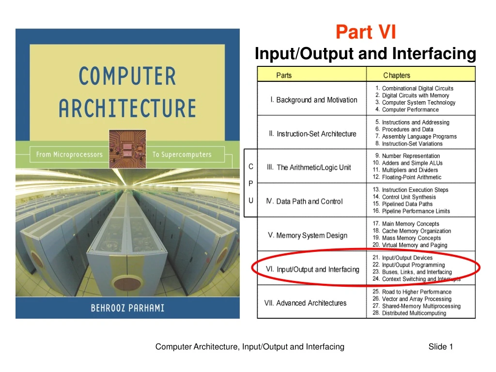
Part VI Input/Output and Interfacing. VI Input/Output and Interfacing. Effective computer design & use requires awareness of: I/O device types, technologies, and performance Interaction of I/O with memory and CPU Automatic data collection and device actuation.

E N D
Part VIInput/Output and Interfacing Computer Architecture, Input/Output and Interfacing
VI Input/Output and Interfacing • Effective computer design & use requires awareness of: • I/O device types, technologies, and performance • Interaction of I/O with memory and CPU • Automatic data collection and device actuation Computer Architecture, Input/Output and Interfacing
21 Input/Output Devices • Learn about input and output devices as categorized by: • Type of data presentation or recording • Data rate, which influences interaction with system Computer Architecture, Input/Output and Interfacing
Section 21.1: Introduction Section 21.3 Section 21.4 Section 21.2 Section 21.5: Other devices Section 21.6: Networked I/O Computer Architecture, Input/Output and Interfacing
21.1 Input/Output Devices and Controllers • Table 3.3 Some input, output, and two-way I/O devices. Computer Architecture, Input/Output and Interfacing
Simple Organization for Input/Output • Figure 21.1 Input/output via a single common bus. Computer Architecture, Input/Output and Interfacing
Proprietary Standard I/O Organization for Greater Performance • Figure 21.2 Input/output via intermediate and dedicated I/O buses (to be explained in Chapter 23). Computer Architecture, Input/Output and Interfacing
21.2 Keyboard and Mouse Computer Architecture, Input/Output and Interfacing
Keyboard Switches and Encoding Figure 21.3 Two mechanical switch designs and the logical layout of a hex keypad. Computer Architecture, Input/Output and Interfacing
Pointing Devices Computer Architecture, Input/Output and Interfacing
How a Mouse Works Figure 21.4 Mechanical and simple optical mice. Computer Architecture, Input/Output and Interfacing
21.3 Visual Display Units Figure 21.5 CRT display unit and image storage in frame buffer. Computer Architecture, Input/Output and Interfacing
How Color CRT Displays Work Figure 21.6 The RGB color scheme of modern CRT displays. Computer Architecture, Input/Output and Interfacing
Besides hue, saturation is used to affect the color’s appearance (high saturation at the top, low saturation at the bottom) Encoding Colors in RGB Format Computer Architecture, Input/Output and Interfacing
Flat-Panel Displays Figure 21.7 Passive and active LCD displays. Computer Architecture, Input/Output and Interfacing
Other Display Technologies Computer Architecture, Input/Output and Interfacing
21.4 Hard-Copy Input/Output Devices Figure 21.8 Scanning mechanism for hard-copy input. Computer Architecture, Input/Output and Interfacing
Same dot matrix size, but with greater resolution Character Formation by Dot Matrices Figure 21.9 Forming the letter “D” via dot matrices of varying sizes. Computer Architecture, Input/Output and Interfacing
Simulating Intensity Levels via Dithering Forming five gray levels on a device that supports only black and white (e.g., ink-jet or laser printer) Using the dithering patterns above on each of three colors forms 5 5 5 = 125 different colors Computer Architecture, Input/Output and Interfacing
Simple Dot-Matrix Printer Mechanism Computer Architecture, Input/Output and Interfacing
Common Hard-Copy Output Devices Figure 21.10 Ink-jet and laser printers. Computer Architecture, Input/Output and Interfacing
How Color Printers Work Red Green The RGB scheme of color monitors is additive: various amounts of the three primary colors are added to form a desired color Blue Absence of green Cyan Magenta The CMY scheme of color printers is subtractive: various amounts of the three primary colors are removed from white to form a desired color To produce a more satisfactory shade of black, the CMYK scheme is often used (K = black) Yellow Computer Architecture, Input/Output and Interfacing
Illusion of full color created with CMYK dots The CMYK Printing Process Computer Architecture, Input/Output and Interfacing
Color Wheels Artist’s color wheel, used for mixing paint Subtractive color wheel, used in printing (CMYK) Additive color wheel, used for projection Primary colors appear at center and equally spaced around the perimeter Secondary colors are midway between primary colors Tertiary colors are between primary and secondary colors Source of this and several other slides on color: http://www.devx.com/projectcool/Article/19954/0/ (see also color theory tutorial: http://graphics.kodak.com/documents/Introducing%20Color%20Theory.pdf) Computer Architecture, Input/Output and Interfacing
21.5 Other Input/Output Devices Computer Architecture, Input/Output and Interfacing
Sensors and Actuators Collecting info about the environment and other conditions Light sensors (photocells) Temperature sensors (contact and noncontact types) Pressure sensors Figure 21.11 Stepper motor principles of operation. Computer Architecture, Input/Output and Interfacing
21.6 Networking of Input/Output Devices Figure 21.12 With network-enabled peripherals, I/O is done via file transfers. Computer Architecture, Input/Output and Interfacing
Input/Output in Control and Embedded Systems Figure 21.13 The structure of a closed-loop computer-based control system. Computer Architecture, Input/Output and Interfacing
22 Input/Output Programming • Like everything else, I/O is controlled by machine instructions • I/O addressing (memory-mapped) and performance • Scheduled vs demand-based I/O: polling vs interrupts Computer Architecture, Input/Output and Interfacing
22.1 I/O Performance and Benchmarks Example 22.1: The I/O wall An industrial control application spent 90% of its time on CPU operations when it was originally developed in the early 1980s. Since then, the CPU component has been upgraded every 5 years, but the I/O components have remained the same. Assuming that CPU performance improved tenfold with each upgrade, derive the fraction of time spent on I/O over the life of the system. Solution Apply Amdahl’s law with 90% of the task speeded up by factors of 10, 100, 1000, and 10000 over a 20-year period. In the course of these upgrades the running time has been reduced from the original 1 to 0.1 + 0.9/10 = 0.19, 0.109, 0.1009, and 0.10009, making the fraction of time spent on input/output 52.6, 91.7, 99.1, and 99.9%, respectively. The last couple of CPU upgrades did not really help. Computer Architecture, Input/Output and Interfacing
Types of Input/Output Benchmark Supercomputer I/O benchmarks Reading large volumes of input data Writing many snapshots for checkpointing Saving a relatively small set of results I/O data throughput, in MB/s, is important Transaction processing I/O benchmarks Huge database, but each transaction fairly small A handful (2-10) of disk accesses per transaction I/O rate (disk accesses per second) is important File system I/O benchmarks File creation, directory management, indexing, . . . Benchmarks are usually domain-specific Computer Architecture, Input/Output and Interfacing
22.2 Input/Output Addressing Figure 22.1 Control and data registers for keyboard and display unit in MiniMIPS. Computer Architecture, Input/Output and Interfacing
Hardware for I/O Addressing Figure 22.2 Addressing logic for an I/O device controller. Computer Architecture, Input/Output and Interfacing
Data Input from Keyboard Example 22.2 Write a sequence of MiniMIPS assembly language instructions to make the program wait until the keyboard has a symbol to transmit and then read the symbol into register $v0. Solution The program must continually examine the keyboard control register, ending its “busy wait” when the R bit has been asserted. lui $t0,0xffff # put 0xffff0000 in $t0 idle: lw $t1,0($t0) # get keyboard’s control word andi $t1,$t1,0x0001 # isolate the LSB (R bit) beq $t1,$zero,idle # if not ready (R = 0), wait lw $v0,4($t0) # retrieve data from keyboard This type of input is appropriate only if the computer is waiting for a critical input and cannot continue in the absence of such input. Computer Architecture, Input/Output and Interfacing
Data Output to Display Unit Example 22.3 Write a sequence of MiniMIPS assembly language instructions to make the program wait until the display unit is ready to accept a new symbol and then write the symbol from $a0 to the display unit. Solution The program must continually examine the display unit’s control register, ending its “busy wait” when the R bit has been asserted. lui $t0,0xffff # put 0xffff0000 in $t0 idle: lw $t1,8($t0) # get display’s control word andi $t1,$t1,0x0001 # isolate the LSB (R bit) beq $t1,$zero,idle # if not ready (R = 0), wait sw $a0,12($t0) # supply data to display unit This type of output is appropriate only if we can afford to have the CPU dedicated to data transmission to the display unit. Computer Architecture, Input/Output and Interfacing
22.3 Scheduled I/O: Polling Examples 22.4, 22.5, 22.6 What fraction of a 1 GHz CPU’s time is spent polling the following devices if each polling action takes 800 clock cycles? Keyboard must be interrogated at least 10 times per second Floppy sends data 4 bytes at a time at a rate of 50 KB/s Hard drive sends data 4 bytes at a time at a rate of 3 MB/s Solution For keyboard, divide the number of cycles needed for 10 interrogations by the total number of cycles available in 1 second: (10 800)/109 0.001% The floppy disk must be interrogated 50K/4 = 12.5K times per sec (12.5K 800)/109 1% The hard disk must be interrogated 3M/4 = 750K times per sec (750K 800)/109 60% Computer Architecture, Input/Output and Interfacing
22.4 Demand-Based I/O: Interrupts Example 22.7 Consider the disk in Example 22.6 (transferring 4 B chunks of data at 3 MB/s when active). Assume that the disk is active 5% of the time. The overhead of interrupting the CPU and performing the transfer is 1200 clock cycles. What fraction of a 1 GHz CPU’s time is spent attending to the hard disk drive? Solution When active, the hard disk produces 750K interrupts per second 0.05(750K1200)/109 4.5% (compare with 60% for polling) Note that even though the overhead of interrupting the CPU is higher than that of polling, because the disk is usually idle, demand-based I/O leads to better performance. Computer Architecture, Input/Output and Interfacing
Interrupt Handling Upon detecting an interrupt signal, provided the particular interrupt or interrupt class is not masked, the CPU acknowledges the interrupt (so that the device can deassert its request signal) and begins executing an interrupt service routine. 1. Save the CPU state and call the interrupt service routine. 2. Disable all interrupts. 3. Save minimal information about the interrupt on the stack. 4. Enable interrupts (or at least higher priority ones). 5. Identify cause of interrupt and attend to the underlying request. 6. Restore CPU state to what existed before the last interrupt. 7. Return from interrupt service routine. The capability to handle nested interrupts is important in dealing with multiple high-speed I/O devices. Computer Architecture, Input/Output and Interfacing
22.5 I/O Data Transfer and DMA Figure 22.3 DMA controller shares the system or memory bus with the CPU. Computer Architecture, Input/Output and Interfacing
DMA Operation Figure 22.4 DMA operation and the associated transfers of bus control. Computer Architecture, Input/Output and Interfacing
22.6 Improving I/O Performance Example 22.9: Effective I/O bandwidth from disk Consider a hard disk drive with 512 B sectors, average access latency of 10 ms, and peak throughput of 10 MB/s. Plot the variation of the effective I/O bandwidth as the unit of data transfer (block) varies in size from 1 sector (0.5 KB) to 1024 sectors (500 KB). Solution 5 MB/s 0.05 MB/s Figure 22.5 Computer Architecture, Input/Output and Interfacing
Distributed Input/Output Figure 22.6 Example configuration for the Infiniband distributed I/O. Computer Architecture, Input/Output and Interfacing
23 Buses, Links, and Interfacing • Shared links or buses are common in modern computers: • Fewer wires and pins, greater flexibility & expandability • Require dealing with arbitration and synchronization Computer Architecture, Input/Output and Interfacing
23.1 Intra- and Intersystem Links Figure 23.1 Multiple metal layers provide intrasystem connectivity on microchips or printed-circuit boards. Computer Architecture, Input/Output and Interfacing
Cross section of metal layers Multiple Metal Layers on a Chip or PC Board Active elements and their connectors Modern chips have 8-9 metal layers Upper layers carry longer wires as well as those that need more power Computer Architecture, Input/Output and Interfacing
Intersystem Links Figure 23.2 Example intersystem connectivity schemes. Figure 23.3 RS-232 serial interface 9-pin connector. Computer Architecture, Input/Output and Interfacing
Intersystem Communication Media Figure 23.4 Commonly used communication media for intersystem connections. Computer Architecture, Input/Output and Interfacing
Comparing Intersystem Links Table 23.1 Summary of three interconnection schemes. Computer Architecture, Input/Output and Interfacing
1 1 0 0 2 2 n–1 n–1 3 3 n–2 n–2 23.2 Buses and Their Appeal Point-to-point connections between n units require n(n – 1) channels, or n(n – 1)/2 bidirectional links; that is, O(n2) links Bus connectivity requires only one input and one output port per unit, or O(n) links in all Computer Architecture, Input/Output and Interfacing
Bus Components and Types Figure 23.5 The three sets of lines found in a bus. • A typical computer may use a dozen or so different buses: • Legacy Buses: PC bus, ISA, RS-232, parallel port • Standard buses: PCI, SCSI, USB, Ethernet • Proprietary buses: for specific devices and max performance Computer Architecture, Input/Output and Interfacing