Download
1 / 10
100 likes | 252 Vues
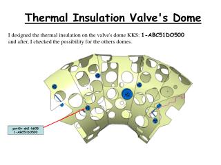
port3r-dn2-h605 1-ABC51DO500. Thermal Insulation Valve's Dome. I designed the thermal insulation on the valve's dome KKS: 1-ABC51DO500 and after, I checked the possibility for the others domes. Assembly procedure step by step.

E N D
port3r-dn2-h605 1-ABC51DO500 Thermal Insulation Valve's Dome I designed the thermal insulation on the valve's dome KKS: 1-ABC51DO500 and after, I checked the possibility for the others domes.
Assembly procedure step by step • In the first time, we have changed the Temporary support, to allow the assembly procedure of the Thermal insulation. New Temporary Support Old Temporary Support I propose to change the length of rings, and remove the top part of the old support.
Assembly Procedure Thermal Insulation of the valve's dome: 1 – Assembly the Outer Vessel Shield on the Outer Vessel (OV) a - Before the assembly, we have clamped the copper tresses on the OV Shield b - Before the mounting we put of extensions (a Tongue) on the OV shield at some place define before to fix the disc on the OV shield. (See sketch 1) 2 – To insert the OV with the OV shield on the Magnet system a - We consider a efficient gap of 20mmfor the mounting Procedure between the OV shield and the Valve's Dome b - We consider the geometrical tolerances are given by DWE (see Appendix I,II) 3 –We make the thermal contact between the OV shield and the valves a– This thermal contact is done by copper tresses. b - The copper tresses are fixed by riveting Step 3
RintDome = 130,5mm Minimum Mounting space 20mm Disc Shield Rivet Rtongue = 100mm Tongue RDisc = 125,5mm OV Shield RintOVShield = 130mm Sketch 1:
4 – We insert the disc to close the Shield a - The disc is inserted by the top, and clamped on the OV shield. b - We consider the geometrical tolerances are given by DWE (see Appendix I,II) 5 – We insert the MLY (M. Pietsch) 6 – weld the OV extension 7 –Close the Dome 8 – Remove the Temporary Support (M. Müller)
Copper Tresses New Temporary Support Picture show the valve assembly
Conclusion: 1 – We do to check the mechanical stresses with the new temporary support. 2 – I have checked the compatibility of the previous solution shown with the others domes, and, if it is possible to change the Temporary support, this solution can be used on the all normal dome 3 – If we take the worst case, we have need a diameter of OV shield = 260mm We consider the tolerance for mounting procedure 20mm, the tolerance of assembly procedure of the dome 7mm, of the Valve 5mm, the tolerance to manufacturing for the dome +2/-3mm at the Diameter and, the tolerance to manufacturing for the OV Shield -3,5mm at the radius. (see Appendix III). 4 – For the special Dome (1-ABC50TG00AEC), there is an other solution of the thermal insulation.
Appendix III RintDome = 130,5mm RintOVShield = 130mm RDisc = 125,5mm RValve = 63mm Minimum Mounting space 20mm +5mm +7mm -1,5mm Valve Disc Shield - 3,5mm RDisc Valve = 30mm Disc Valve