Cisco Router Configuration
Cisco Router Configuration. Eng.Ola Abd El- Latif 1 st June 2010. Introduction to wan. A WAN is a data communications network that spans a large geographic area such as a state, province, or country They connect devices that are separated by wide geographical areas.

Cisco Router Configuration
E N D
Presentation Transcript
Cisco Router Configuration Eng.OlaAbdEl-Latif 1st June 2010
Introduction to wan • A WAN is a data communications network that spans a large geographic area such as a state, province, or country • They connect devices that are separated by wide geographical areas. • They use serial connections of various types to access bandwidth over large geographic areas.
A WAN operates at the physical layer and the data link layer of the OSI reference model. • It interconnects LANs that are usually separated by large geographic areas. • WANs provide for the exchange of data packets and frames between routers and switches and the LANs they support.
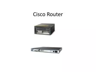
Introduction to routers • Routers offer many services, including internetworking and WAN interface ports. • It has a CPU, memory, a system bus, and various input/output interfaces. • routers connect and allow communication between two networks and determine the best path for data to travel through the connected networks. • routers need the Internetwork Operating System (IOS) software to run configuration files.
These configuration files contain the instructions and parameters that control the flow of traffic in and out of the routers. • Routers use routing protocols to determine the best path for packets. • The configuration file specifies all the information for the correct setup and use of the selected, or enabled, routing and routed protocols on a router.
The Internal Components of a Cisco Router • DRAM(dynamic random access memory) • Used to hold packet buffers, ARP cache, routing tables. • Running-config also stored in RAM, and most routers expand the IOS from flash into RAM upon boot.
ROM(read-only memory) • Used to start and maintain the router. Holds the POST and the bootstrap program, as well as the mini-IOS. • Flash memory (EEPROM : electronically erasable programmable read-only memory ) • Stores the Cisco IOS , Not erased when the router is reloaded
NVRAM(nonvolatile RAM) • Holds router (& switch) configurations • Not erased when the router is reloaded • Does not store an IOS. • Bootstrap • Stored in the microcode of the ROM, the bootstrap is used to bring a router up during initialization. It will boot the router and then load the IOS.
POST(power-on self-test) • Stored in the microcode of the ROM, the POST is used to check the basic functionality of the router hardware and determines which interfaces are present.
Console port (used for configuring router) • Interfaces (or ports) – LAN/WAN connections
The Router Boot Sequence • Step 1: • The router performs a POST. • The POST tests the hardware to verify that all components of the device are operational and present. For example, the POST checks for the different interfaces on the router.
Step 2: • If it passes, The bootstrap then looks for and loads the Cisco IOS software. • By default, the IOS software is loaded from flash memory in all Cisco routers.) • The default order of an IOS loading from a router is Flash, TFTP server, then ROM.
Step 3: • The IOS software looks for a valid configuration file stored in NVRAM. • This file is called startup-config and is only there if an administrator copies the running-config file into NVRAM.
Step 4: • If a startup-config file is in NVRAM, the router will copy this file and place it in DRAM and call the file running-config. • The router will use this file to run the router. • The router should now be operational.
Step 5: • If a startup-config file is not in NVRAM, the router will broadcast out any interface that detects carrier detect (CD) for a TFTP host looking for a configuration, • and when that fails, it will start the setup mode configuration process
The Cisco Internetwork Operating System (IOS): • Cisco IOS is the kernel of Cisco routers and most switches. • These are some important things that the Cisco router IOS software is responsible for: • Carrying network protocols and functions • Connecting high-speed traffic between devices • Adding security to control access and stop unauthorized network use • Providing scalability for ease of network growth and redundancy • Supplying network reliability for connecting to network resources
Connecting to a Cisco Router • You can connect to a Cisco router to • configure it. • verify its configuration. • check statistics. • You can access the Cisco IOS through • the console port of a router, • from a modem into the auxiliary (or Aux) port, • or even through Telnet.
Management port connections • This page will introduce the console and auxiliary (AUX) ports, which are also known as the management ports. • These asynchronous serial ports are not designed as networking ports. • The console port is required for the configuration of the router. • Not all routers have an auxiliary port. • When the router is first put into service, there are no networking parameters configured.
Direct Config.Console port • is usually an RJ-45 connection located at the back of the router. • by default, there’s may or may not be a password set. • The console port is a management port that is used to provide out-of-band access to a router. • It is used to set up the initial configuration of a router and to monitor it. • The console port is also used for disaster recovery procedures
Indirect Configuration • The router can also be remotely configured through the configuration port across an • IP network using Telnet • or by dialing to a modem connected to the console or auxiliary port on the router.
Auxiliary port • which is the same thing as a console port. • But an auxiliary port also allows you to configure modem commands so that a modem can be connected to the router. • Using Aux port allow you to dial up a remote router and attach to the auxiliary port if the router is down and you need to configure it out-of-band (meaning out of the network).
the program Telnet. • The third way to connect to a Cisco router is in-band, through the program Telnet. • ( In-band ) means configuring the router through the network. • Telnet is a terminal emulation program that acts as though it’s a dumb terminal. • You can use Telnet to connect to any active interface on a router, such as an Ethernet or serial port.
Configuring a Single Cisco Router Router ModesMoving between modesConfiguring a Router NameSetting the PasswordsPassword Encryption Router Interfaces Configuring a Fast Ethernet Interface Configuring a Serial Interface Configuration Commands Show commands
Note that : • In normal cases the interface will attached to a CSU/DSU type of device that provides clocking for the line to the router, you can use the serial interface to connect to a DCE network via a CSU/DSU that provides the clocking to the router interface. • But if you have a back-to-back configuration (serial – serial ), one end— the data communication equipment (DCE) —must provide clocking and bandwidth , while the other end DTE (data terminal equipment) is not set to provide clocking.
Collision domain and broadcast domain: • The LAN that use hub to connect together, this network have one broadcast domain and one collision domain. • A switch (and bridge) breaking up collision domains But make the network is still one broadcast domain • Routers break up a broadcast domain —the set of all devices on a network segment that hear all the broadcasts sent on that segment. Also break collision domain. • Remember that Switches separate Collision domains and Routers separate Broadcast domains (as well as collision domains)
Broadcast Domain #1(1) Hub1 to Switch1 is part of the same collision domain as the other connections out of Hub1 (2) Switch1 has a collision domain on its connection out the top of the device in the diagram (3) Switch1 to Router1 is a collision domain
Broadcast Domain #2(1) Router1 to Switch2 is a collision domain (2) Switch2 to Router2 is a collision domain • Broadcast Domain #3(1) Router2 to Bridge1 is a collision domain(2) Bridge1 has a collision domain on its connection out the right of the device in the diagram • Total Broadcast Domains = 3Total Collision Domains = 7
Ethernet Cabling : • Three types of Ethernet cables are available: • Straight-through cable • Crossover cable • Rolled cable
Straight-Through Cable • Four wires are used in straight-through cable to connect Ethernet devices. • It is relatively simple to create this type.
Crossover Cable • The same four wires are used in this cable as in the straight-through cable; • we just connect different pins together, as shown in figure.
Rolled Cable • Although rolled cable isn’t used to connect any Ethernet connections together, • You can use a rolled Ethernet cable to connect a host to a router console serial communication (com) port.
How to connect devices??? • NIC, Router, Access point, Networked Printer Transmit on 1 ,2 and Receive on 3,6 • Hub, Switch Devices Transmit on 3,6 and Receive on 1,2 • We want to connect transmitter pins with receiver pins so that and according to above information, and as an example: to connect • - Switch to switch == use crossover cable • - Router to switch or hub == use straight cable
Routing • Routing is taking a packet from one device and sending it through the network to another device on a different network. • The router learns about remote networks from neighbor routers or from an administrator. • The router then builds a routing table (a map of the internetwork) that describes how to find the remote networks. • If a network is directly connected, then the router already knows how to get to it.
If a network isn’t directly connected to the router, the router must use one of two ways to learn how to get to the remote network: • static routing • dynamic routing
static routing • meaning that someone must hand-type all network locations into the routing table • dynamic routing • In dynamic routing, a protocol on one router communicates with the same protocol running on neighbor routers. • The routers then update each other about all the networks they know about and place this information into the routing table. • If a change occurs in the network, the dynamic routing protocols automatically inform all routers about the event.
The administrative distance (AD) • is used to rate the trustworthiness of routing information received on a router from a neighbor router. An administrative distance is an integer from 0 to 255, where 0 is the most trusted and 255 means no traffic will be passed via this route.
If a router receives two updates listing the same remote network, • the first thing the router checks is the AD. • If one of the advertised routes has a lower AD than the other, then the route with the lowest AD will be placed in the routing table.
If both advertised routes to the same network have the same AD, then routing protocol metrics (such as hop count or bandwidth of the lines) will be used to find the best path to the remote network.
In the Static routing : • There is no overhead on the router CPU • Here the overhead on administrator so that any change on the network the administrator had to add or modify the route. • There is no bandwidth usage between routers. • It adds security because the administrator can choose to allow routing access to certain networks only. • It’s not feasible in large networks because maintaining it would be a full-time job in itself.