Download
1 / 18
180 likes | 288 Vues
This paper presents a methodology to measure propagation delay over an 8B/10B coded link spanning 100 km of fiber optics. A 3.125 Gbps serial link implemented in FPGA achieves a precision resolution of 320 ps, making it suitable for general measurement and control applications. The approach is applicable to complex systems like KM3NeT and the LHC, where synchronization and precise timing are crucial. A test setup utilizing Xilinx hardware demonstrates effective measurement techniques, highlighting the potential for existing serial channels in high-precision timing applications.

E N D
Measuring propagation delay over a coded serial communication channel using FPGAs P.P.M. Jansweijer, H.Z. Peek VLVnT-09 Athens
Introduction It is feasible to measure propagation delay over an 8B/10B coded link over 100 Km of fibre A 3.125 Gbps serial link implemented in FPGA provides a resolution of 320 ps. The method presented originates from thinking about KM3NeT timing… …but applies more general to “Measurement and control applications” VLVnT-09 Athens
Measurement and control application example - I KM3NeT OM OM OM OM OM OM OM OM 1 Km GPS Shore Station Distributed: 1 cubic Kilometer 1 Km Synchronize system timing High precision: ~ 1 ns 1 Km VLVnT-09 Athens
Measurement and control application example - II (Super) LHC P5 P4 Distributed: LHC diameter 8,6 Km P2 CCR Synchronize system timing High precision: aim < 100 ps P8 TTC backbone From a presentation given at the ATLAS Upgrade "ROD" Workshop Sophie Baron – CERN June 18, 2009 TTC off-detector TTC on-detector VLVnT-09 Athens
Measurement and control application common Distributed Large systems which (often) use (serial) communication channels Synchronize system timing Know the time offsets between clocks in the system Measure offsets = measure propagation delay • Could we use existing serial communication channels to measure propagation delay? VLVnT-09 Athens
Serial Communication Coding Properties Clock & Data coded into one stream DC-Balance Special code-groups / Word Alignment 1 2 3 1 3 VLVnT-09 Athens
Measure propagation delay with high precision Lock the Receiver to Transmitter Clock => Clocks are Isochronous: Use the same time reference But have an offset Use SerDes Word Alignment information Resolution one Unit-Interval (bit time) Using property and is just a hardware implementation on the OSI-model Data Link layer that is transparent to higher levels of hierarchy: IEEE 802.3 “CSMA/CD” (Ethernet) IEEE 1588 “Precision Clock Synchronization Protocol” 1 3 1 3 VLVnT-09 Athens
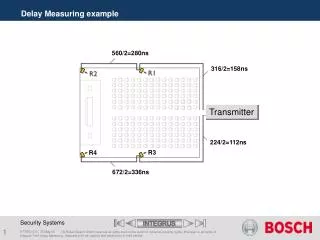
Measure propagation delay using FPGA SerDes Word Alignment information @ 3.125 Gbps Test setup block diagram Xilinx ML507 Board Lattice LFSCM25 Xilinx Virtex-5 SerDes SerDes 156.25 MHz 156.25 MHz Test-Bed Transmitter Test-Bed Receiver Lattice SC PCI Expressx1 Evaluation Board 100 Km fiber LEDs Start Stop VLVnT-09 Athens
Test setup transmission scheme Tx 8B/10B Encoded K28.5 D16.2 K23.7 Dx.y K28.5 D16.2 K28.5 D16.2 K28.5 D16.2 K28.5 D16.2 IDLE CharExt IDLE IDLE IDLE IDLE Start 2 x 50 Km fiber ~ 490 us Stop Rx 8B/10B Encoded K28.5 D16.2 K28.5 D16.2 K28.5 D16.2 K28.5 D16.2 K23.7 Dx.y K28.5 D16.2 IDLE IDLE IDLE IDLE CharExt IDLE 3.125 Gbps / 20 bits = 156.25 MHz system speed (6.4 ns)Without additional information the Stop Time is known with a 6.4 ns resolution VLVnT-09 Athens
Real Test setup 50 Km fiber 50 Km fiber Start Stop Test-bed Receiver Test-bed Transmitter RX (Stop) Xilinx Virtex-5 Board (ML507) TX (Start) Lattice LFSCM25 Board VLVnT-09 Athens
Measuring varying propagation delay +0 ps +700 ps Constant Impedance Trombone Line Resynchronize… What is happening? Reset (= resynchronize) VLVnT-09 Athens
What happens during resynchronization TX is transmitting a serial bit stream based on the reference clock RX using the reference clock to try to lock its PLL in the CDR onto the incoming bit stream (note: usually the TX and RX reference clock do not have the same source...) Once the PLL in the CDR is in phase, RX switches over from its reference clock to the RX recovered clock “RxRecClk” (this happens on a random bit) Next the Word Aligner is searching for a “Comma” Once a Comma is found the word aligner knows how to set its multiplexer and feed properly aligned sets of 20 bits to the FPGA fabric VLVnT-09 Athens
Test setup block diagram Xilinx ML507 Board Lattice LFSCM25 Xilinx Virtex-5 SerDes SerDes 156.25 MHz 156.25 MHz Test-Bed Transmitter Test-Bed Receiver Lattice SC PCI Expressx1 Evaluation Board 100 Km fiber LEDs Start Stop VLVnT-09 Athens
Resynchronization in action 011101011000001010110111010110000010101101110101 3 1 0 RxRecClk BitSlide(4:0) 0 0001 = 1 0 0000 = 0 0 0011 = 3 Start/Stop delay Algorithm: Propagation Delay = “Start-Stop” Delay + “LED Value” * 320 ps VLVnT-09 Athens
Algorithm Propagation Delay: “Start-Stop” Delay + “LED Value” * 320 ps 0 ps 320 ps 960 ps Leds: “00000” * 320 ps delay => “add 0 ps” Leds: “00001” * 320 ps delay => “add 320 ps” Leds: “00011” * 320 ps delay => “add 960 ps” Start/Stop delay VLVnT-09 Athens
Add delay and Resynchronize + 320 ps 111010110000010101101110101100000101011011101011 111010110000010101101110101100000101011011101011 19 19 0 RxRecClk BitSlide(4:0) 6.4 ns 320 ps 1 0011 = 19 0 0000 = 0 Algorithm: Propagation Delay = “Start-Stop” Delay + “LED Value” * 320 ps VLVnT-09 Athens
FPGA SerDes remarks The Receiver Deserializer should provide a means to (manually control) “Bit Slip”. Tested in: Implementation verified at CEA-SACLAY VLVnT-09 Athens
Conclusion It is feasible to measure propagation delay over an 8B/10B coded link over 100 Km of fibre. A 3.125 Gbps serial link provides a resolution of 320 ps. This can be implemented in an FPGA Thank you VLVnT-09 Athens