Download
1 / 14
140 likes | 343 Vues
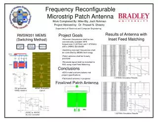
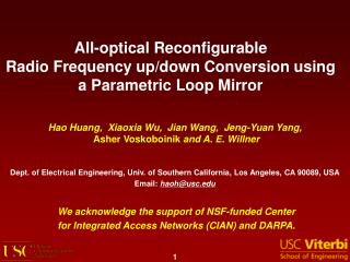
All-optical Reconfigurable Radio Frequency up/down Conversion using a Parametric Loop Mirror. Hao Huang, Xiaoxia Wu, Jian Wang, Jeng-Yuan Yang, Asher Voskoboinik and A. E. Willner. Dept. of Electrical Engineering, Univ. of Southern California, Los Angeles, CA 90089, USA

E N D
All-optical Reconfigurable Radio Frequency up/down Conversion using a Parametric Loop Mirror Hao Huang, Xiaoxia Wu, Jian Wang, Jeng-Yuan Yang, Asher Voskoboinik and A. E. Willner Dept. of Electrical Engineering, Univ. of Southern California, Los Angeles, CA 90089, USA Email: haoh@usc.edu We acknowledge the support of NSF-funded Center for Integrated Access Networks (CIAN) and DARPA. 1
Outline • Introduction • Concept and Principle • Experimental Results • Up-conversion • Down-conversion • Summary 2
Introduction • Radio frequency up/down conversion might be useful in many microwave photonic applications • All optical up/down conversion can potentially reduce the reliance on the bandwidth of electrical circuit and enable up-conversion to a higher frequency. • Reconfigurable up/down conversion with higher dynamic range is highly required for different applications SSB CS-DSB Signal Freq. domain ω ω Up ω ωs ωs ωs Down 0 1 0 1 0 1 0 1 Time domain t t Baseband or IF over fiber RF over fiber
Concept and Principle Pumps s- s+ s- s+ Counter Clockwise Clockwise ωP2 ωP2 ωP1 ωP1 ωs ωs Output Input Signal Pumps s- s+ ωs ωs ωP1 ωP2 Potential advantages • Frequency double • Saving optical filters • Increased reconfigurability and dynamic range K. Mori, et. al, Optical Letters, (20) 12, pp 1424-1426 (1995).
Experimental Setup 400-m ZDW: ~1557nm 1-km 17ps/nm/km To suppress SBS of pumps Without destroying signals
Single Channel Up-conversion 40GHz 48GHz 60GHz 20GHz 7.5Gbit/s@60GHz 2.5Gbit/s@20GHz 5Gbit/s@40GHz 6Gbit/s@48GHz Demodulation
Operating Bandwidth First order FWM Input signal Idlers (S+ and S-) Second order FWM Power Ratio of Port2 Frequency spacing of two pumps: 20GHz, SMF:1-km • Power ratio is dependent on the wavelength of pumps and signals, as well as dispersion of the DE. • 2nd FWM are suppressed inherently, higher harmonic suppression ratio is expected
Suppression Ratio and Power dependence Suppression ratio vs Up-conversion frequency BER vs Signal Power Received power for BER of 10-9 • >20 dB carrier suppression and harmonic suppression ratio of optical spectrum for up to 60GHz • >18dB harmonic suppression ratio of electrical spectrum for up to 48GHz • Optimal signal power decreases when the pump power is increased.
4-Channels Up-conversion Simultaneously Optical Spectrum BER Measurement Ch.1 Ch.3 Ch.2 Ch.4 10dB/div 0.9nm/div Eye-diagram of Up-converted Signal after demodulation 4 2 1 3 100ps/div 100ps/div 100ps/div 100ps/div • 4-Channels WDM base-band signals are up-converted simultaneously and demodulated. • 0.4dB power penalty on average for 20km fiber transmission
Principle of Down-conversion Pumps Pumps s- s+ Counter Clockwise s- s+ Clockwise ωs ωP2 ωP1 ωs ωP2 ωP1 Output Input Input Pumps s+ s- ωs ωs ωP1 ωP2 Down-conversion can be achieved by using the same setup.
Single Channel Down-conversion 40GHz 40GHz 10dB/div 0.5nm/div 0.5nm/div Output down-converted signal Input CS-ROF signal 100ps/div CS-ROF signal (2.5Gbit/s@40GHz) is down-converted using the same set-up. 2.5Gbit/s
4-Channel WDM Signal Down-conversion BER Measurement Optical Spectrum Ch 4 Ch 2 Ch 3 Ch 1 10dB/div 2nm/div Down-converted Eye-diagram 1 3 4 2 100ps/div 100ps/div 100ps/div 100ps/div • 4-Channels WDM CS-ROF signals are down-converted simultaneously. • 0.8dB power penalty on average for 20km fiber transmission.
Summary • A method of reconfigurable up/down conversion using a parametric loop mirror is proposed. • Up-conversion of up to 60GHz and down-conversion from 40GHz are demonstrated. • WDM signals simultaneously up/down-conversion are achieved. • The proposed method can save optical filters and has a higher dynamic range.