Download
1 / 27
270 likes | 289 Vues
Explore the advantages of formal methods in software engineering with abstract models such as CHAM and Alloy. Learn about their features, benefits, analysis, and design faults to understand software architecture better.

E N D
Formal Methods in SE Abstract Model Specification Lecture # 19
Advantages • The flexibility to model a specification which can directly lead to the code. • Easy to understand • A large class of structural models can be described in Z without higher – order features, and can thus be analyzed efficiently. • Independent Conditions can be added later
Chemical Abstract Model CHAM: for architectural description and analysis. Software Systems chemicals (whose reactions are controlled by explicitly stated rules). Where floating molecules can only interact according to a stated set of reaction rules.
Features(CHAM) - Modular specification • Chemical reactions • Molecules (components) • Reactions (Connectors) • Solutions (States of CHAM) • This is used in areas where intended architecture will tend to be large, complex, and assembled from existing components. • Architectural elements: Processing elements, data elements, and connecting elements.
Introduction • Alloy • Is a modeling notation that describes structural properties • Has a declaration syntax compatible with graphical object models • Has a “set-based” formula syntax • Is based on “Z”
Example File System contents ! ! Object DirEntry Name name Parent (~children) ! entries Dir File Root!
Example (File System) model FileSystem { domain {Object, DirEntry, fixed Name} state { partition File, Dir: static Object Root: fixed Dir! entries: Dir! -> DirEntry name: DirEntry -> static Name! contents: DirEntry -> static Object! parent (~children) : Object -> Dir } def parent {all o | o.parent = o.~contents.~entries} inv UniqueNames {all d | all e1, e2: d.entries | e1.name = e2.name -> e1 = e2} inv Parents { no Root.parent all d: Dir – Root | one d.parent} inv Acyclic {no d | d in d.+parent} inv Reachable {Object in Root.*children} cond TwoDeep {some Root.children.children} assert FileHasEntry {all o | sole o.parent} assert AtMostOneParent {all o | sole o.parent} op NewDirEntries (d: Dir, es: DirEntry’) { no es & DirEntry d.entries’ = d.entries + es all x: Dir – d | x.entries’ = x.entries } op Create (d: Dir!, o: Object’!, n: Name) { n! in d.entries.name some e: DirEntry’ | NewDirEntries (d, e) && e.contents’ = o && e.name’ = n} assert EntriesCreated {all d: Dir, e: DirEntry’ | NewDirEntries (d, e) -> DirEntry’ = DirEntry + e} assert CreateWorks {all d, o, n | Create (d, o, n) -> o n d.children’} }
Example (File System) • Structure of the model • Domain paragraph • State paragraph • Definition paragraph • Invariants • Condition • Assertions • Operations • Assertions
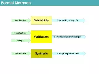
Analysis • Alloy supports two kinds of analysis • Simulation: Consistency of an invariant or operation is demonstrated by generating a state or transition. • Checking: A consequence of a specification is tested by attempting to generate a counterexample. • Together they enable an incremental process of specification.
Based On Z • Alloy is based on Z because: • Simple and intuitive semantics (based on sets). • Well suited for object oriented modeling. • Data structures are built from concrete mathematical structures.
Features • Automatic analysis • Theorem proving is deep & automatic. • Easier to read and write. Plain ASCII notation. • Relational operators are powerful. • Incorporates mutability notions from informal notations.
Design Faults • Omission of the let construct & relational operators • No integers • No distinction between attributes and relations
Formalizing Style to Understand Descriptions of Software Architecture
Introduction • Software architecture describes a software system • Architectural descriptions are informal & diagrammatic • Represented by boxes & lines • For one system they may mean filters & pipes • For another system boxes abstract data types or objects & lines procedure calls
Introduction • Different graphical conventions used to describe more than one kind of component or connection type in a single system • Generalized meanings to architectural descriptions
How is it done? • Formalize abstract syntax for architectures • For a given style: • Define the semantic model • Discuss concrete syntax for easing syntactic descriptions in a given style • Define the mapping from abstract syntax into semantic model • Make explicit the constraints on the syntax
How is it done? • Demonstrate analysis within & between formally defined architectural styles
Abstract Syntax of Software Architectures • Component: • Relationship between component & it’s environment is defined as a collection of interaction points or ports: • [PORT, COMPDESC] Component ports : P PORT description : COMPDESC
Abstract Syntax of Software Architectures • Connectors: • Connector has an interface that consists of a set of roles: • [ROLE, CONNDESC] Connector roles : P ROLE description : CONNDESC
Abstract Syntax of Software Architectures • Instances of components & connectors are identified by naming elements from the syntactic class [COMPNAME, CONNNAME] PortInst == COMPNAME x PORT RoleInst == CONNNAME x ROLE
Step 1 (Define Semantic Model) Filter Alphabet : DATAPORT P DATAPORT States : P STATE Inputs, outputs : P DATAPORT Start : STATE Transitions : (STATE x (DATAPORT seq DATA)) (STATE x (DATAPORT seq DATA)) Inputs n outputs = o Dom alphabet = inputs u outputs Start e states • s1, s2 : STATE ; ps1, ps2 : DATAPORT seq DATA • ((s1, ps1), (s2, ps2)) e transitions • s1 e states L s2 e states • L dom ps1 = inputs L dom ps2 = outputs • L ( i : inputs • ran (ps1(i)) alphabet(i)) • L ( o : outputs • ran (ps2(o)) alphabet(o))
Step 1 (Define Semantic Model) Pipe source, sink : DATAPORT alphabet : P DATA source = sink
Step 2 Define Concrete Syntax FilterDescriptions : P COMPDESC PipeDescription : P CONNDESC
Step 3 • Mapping from Abstract Syntax to Semantic Model PFComp : Connector P Pipe • c : Connector ; p1, p2 : Pipe | p1 PFComp (c ) • p2 PFComp (c ) p1.alphabet = p2.alphabet
Step 4 • Highlight the constraints in the syntax LegalPFComponent Component Description FilterDescriptions
Advantages • Provides a templates for formalizing new architectural styles in a uniform way • Provides uniform criteria for demonstrating that the notational constraints on a style are sufficient to provide meanings for all described systems • Makes possible a unified semantic base through which different stylistic interpretations can be compared