Download

1 / 42
420 likes | 564 Vues
Adaptive Control of Network Centric Dynamic Systems. Jagannathan (Jag) Sarangapani Professor of Department of Electrical and Computer Engineering & Computer Science University of Missouri-Rolla Rolla, Missouri 65409. Tel: 573-341-6775; Email:sarangap@umr.edu &

E N D
Adaptive Control of Network Centric Dynamic Systems Jagannathan (Jag) Sarangapani Professor of Department of Electrical and Computer Engineering & Computer Science University of Missouri-Rolla Rolla, Missouri 65409. Tel: 573-341-6775; Email:sarangap@umr.edu & Site Director, NSF I/UCRC on Intelligent Maintenance Systems
Outline • Overview of Research at my Lab/Center • Energy Aware Protocols • Adaptive Congestion Control • Routing Protocol • Conclusions
Network of Autonomous Robots UMR Mote Requirement: Continuous Communication among 10 robots/unattended sensors OBJECTIVE • Cooperative decision making and control of multiple unattended formation of robots (mobile adhoc networks) with continuous RF communication (UMR mote) BACKGROUND • Network communication among a formation of robots is necessary in order to perform any task. This communication must be present at all times. This communication must be reliable even when the robots are in motion and when energy is limited. This requires a novel distributed hybrid system architecture, reliable communication hardware and energy efficient protocols for communication that guarantees quality of service requirements. APPROACH COST AND SCHEDULE • Milestone 1: Develop distributed embedded hybrid architecture • Milestone 2: Develop wide band communication-based UMR Mote • Milestone 3: Integrate sensors and RF hardware on the robot • Milestone 4: Implement the energy efficient communication protocols using energy delay metric • Milestone 5: Implement control strategy and demonstrate MILESTONES Qtr 1 Qtr 2 Qtr 3 Qtr 4 Milestone 1 Milestone 2 Milestone 3 DELIVERABLES Milestone 4 • UMR RF Mote • Energy Efficient Protocols • Demonstration and Reports Milestone 5 POINT OF CONTACT Total Cost $250K ($K) 75 100 50 25 Dr. J. Sarangapani, Electrical and Computer Eng Dept., UMREmail: sarangap@umr.edu; Phone: 573-341-6775;URL: www.umr.edu/~sarangap 3
Manipulation of Microscale/Nano Scale Objects using Micro/Nano Robots Fig. 1. Image sequences taken at 256 sec intervals without drift compensation (first row) and with drift compensation (second row). The scanned area is 512×512nm2. • Manipulation of a micro-sphere • Pickup a micro-sphere from a planar substrate • Sequence of operations • Lower a probe • Pickup the micro-sphere • Retract the probe • Novel intelligent controllers designed outperform available ones • AFM is used as a feedback for manipulation and drift compensation of nano particles
Prognostics on a Chip Wireless Service History U M R M o t e Database Distributed Sensors Degradation Remaining Useful Life Multivariable Analysis with Learning Trending Confidence Wireless Confidence Severity Wireless U M R M o t e Reliability Information
Monitoring Using Wireless Sensor Networks Sensor Node Base Station Cluster Head Self Organizing Network Detect Damage Progression Diagnosis/Prognosis Emission Control
Auto-ID Solutions for Network-Centric Manufacturing Environments Objective: Develop concepts, models, and prototypes for effective integration of Auto-ID technology in a Network-Centric Manufacturing Environment*, aimed at reducing delays and eliminating non-value added production activities and responding rapidly to unexpected events on the shop floor. • Research Highlight: • Develop techniques for effective use of real-time data provided by Auto-ID technology. • Demonstrate integration of Auto-ID technology with the aircraft manufacturing practice. Application Potential:1) Inventory control of time and temperature sensitive materials 2) Receiving & shipping operations3) Aircraft assembly line flow *Network-centric Manufacturing Environment incorporates a dynamic network of self-organizing, autonomous units that operate, collaborate, cooperate, and compete upon basic principles of decentralization, participation, and coordination in order to accomplish the goals set at system level.
Networking Infrastructure forAdaptive Inventory Management Objective: To demonstrate integration of decision making in a multi-technology environment. Conclusions: (1)Modularity of the architecture facilitates expansion of the application domain and experimentation with complex models, and (2) the infrastructure allows for investigating different networking topologies, protocols, and alternative hardware.
Neural Emission Control Lean operation and with high EGR levels in certain SI Engine can reduce emissions (HC, CO & NOx) by as much as 30% and also it improves fuel efficiency by as much as 5 ~ 10% (Inoue, 1993). Heywood, 1988 Cyclic dispersion without control Objective: Minimize the cyclic dispersion at lean engine operation by applying the NN controller
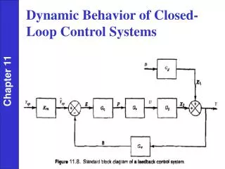
Nonlinear Discrete-time System Nonlinear Back Stepping Back Stepping Non Strict
Comparison of Experimental and Simulation Data Simulation result Experimental data (Sutton, 2000)
NN Output Feedback Lean Emission Control Neural Network (NN) Controller Engine 1 2 3 Control Inputs L Inputs outputs Hidden Layer Measurements NN Observer
Contributions • Nonstrict Feedback Nonlinear Discrete-time Systems introduced and optimal controllers designed • Noncausal control problem is overcome • Separation Principle, Certainty Equivalence, Persistency of Excitation Condition, and Linear in the Unknown Parameters are relaxed • Fuel efficiency improvement by 5 to 10%, NOx by 98% and uHC by 30% was noted
Outline • Overview of Research at ESNL • Energy Aware Protocols • Congestion Control • Routing • Conclusions
Performance Requirements • Congestion causes • Reduced channel capacity • Energy wastage • QoS suffers • Throughput, network efficiency • Delay , jitter • Fairness • Energy-efficiency • Proposed scheme consists of • Congestion prediction and control mechanisms to prevents buffer overflows • Fairness mechanism
Congestion in Wireless Sensor Networks (WSN) • Congestion can be a result of: • Channel fading • Traffic exceeding channel capacity • Note: Typical WSN has only one “sink”
Ways of Alleviating Congestion • Energy aware congestion control • Adaptive Back off Interval scheme • Adaptive energy delay routing * Cross Layer Design is needed
Background • Sensor versus ad hoc • Processing, memory communication and energy constrains in WSN in contrast to ad hoc networks • Previous works • End-to-end protocols (e.g. TCP) • Drawback of large feedback latency (round-trip) • CODA, Fusion • Small processing overhead • Congestion message is broadcasted to throttle traffic, with sources reducing introduced traffic • Use fixed thresholds to initiate flow control • Dropping packets when the congestion occurs
Objectives of Congestion Control • Detection of the congestion and an onset of one • Channel estimation from Distributed Power Control (DPC - our previous work) predicts severe fading and temporarily suspend outgoing and incoming flows • Buffer occupancy used to control incoming/outgoing flows • Quality of Service (QoS) • Weighted Fairness expressed as: where W – throughput, φ – weight • Congestion control using backpressure – a set of three proposed schemes (described later) (1)
Proposed Scheme • Rate-based congestion control with weights changed adaptively • Rate selection to prevent buffer overflow • Rate allocation to flows according to weights (using fair scheduling) • Selection of back-off interval to achieve the selected rate (predictive, distributed, mathematically guaranteed) • (OPTIONAL) Adaptive weights allocated to each packet to improve weighted fairness • Adaptive re-calculation of weights for each packet • Fair scheduling and rate allocation to flows based on adopted weights
Buffer occupancy and Error Dynamics • Consider buffer occupancy at a particular node • where T is the measurement interval, qi(k) is the buffer occupancy of node ‘i’ at time instant k, ui(k) is a regulated (incoming) traffic rate, and fi(k) is an outgoing traffic rate. • Consider the desired buffer occupancy at node i to be qid. Then, buffer occupancy error defined as ei(k)=qi(k)-qid can be expressed as (2) (3)
Rate Selection • Define the traffic rate input, ui(k) as where kv is a gain parameter. • Unknown outgoing traffic is estimated using adaptive scheme where the parameter vector is updated • Selected incoming rate is divided fairly (φj)among incoming flows (4) (5)
Simulation Results for Rate-based Buffer Control Queue utilization and estimation of the outgoing flow. Queue utilization error and outgoing traffic estimation error.
Adaptive Back-off Selection Algorithm • Goal Select back-off interval BOi at i-th transmitting node such that the actual throughput meets the desired outgoing rate fi(k). • Consider inverse of the back-off interval, and call it a virtual rate VRi where VRi is the virtual rate at i-th node, and BOi is the corresponding back-off interval. • NOTE: the virtual rate is not equal to the actual rate; instead, the virtual rate is proportional to the actual rate. (6)
Outgoing Rate Selection • The actual rate of an i-th node is a fraction of the channel bandwidth B(t) defined as where TVRi is the sum of all virtual rates for all neighbor nodes. • Differentiating and transforming into discreet time domain the outgoing rate is equal where (7) (8) (9)
Closed-loop Control of Backoff Selection • Now consider feedback equation for closed-loop controller where âi(k) is estimate of ai(k), and ei(k)=qi(k)-qid is the throughput error • Parameters updates taken as • The closed loop throughput error system with estimation error, ε(k), as (10) (11) (12)
Convergence and Stability • Theorem (General case): • Given the back-off selection scheme above with an interval updated as (10), and with uncertainties estimated by (11), with ε(k) as the error in estimation which is considered bounded above , with εN a known constant. • Then the mean error in throughput and the estimated parameters are bounded provided and hold • where , Kvmax is the maximum singular values of Kv, and σ is the adaptation gain.
Simulation Results Performance for unbalanced tree topology. Weighted delay with equal flow weights (const=0.2).
Impact on Routing Protocol • Hardware limitation explored • Memory limits queue size • Processing limits number of connections that can be handled (also for information aggregation) • Localized congestion • For example due to electro–magnetic interferences • Can be mitigated by selecting a alternative route around the congested area
OEDSR • Optimal Energy Delay Sub-Network Routing (OEDSR) protocol • Maximizes Link Cost Factor (LCF) to perform optimal routing based on network parameters • LCF is given by • Where Ei is the energyin the next node, Di is the delay, and xi is the distance from the next node to the base station • Cluster heads (CH) and relay nodes (RN) are used to route data from a data source to the base station (BS) • Implemented on UMR hardware
OEDSR: Optimal Relay Node CH 1 CH 1 CH 2 1 2 34 5 6 7 CH 2 CH 3 6 7 1 11 1 2 34 5 6 7 2 3 1 12 4 5 6 BS 7 15 6 7 2 8 9 10 13 14 3 7 “HELLO” packet “RESPONSE” packet “HELLO_CH” packet “RELAY_SELECT” packet
OEDSR: Optimal Relay Node CH 1 CH 1 CH 2 1 2 34 5 6 7 CH 2 CH 3 7 6 7 1 11 1 2 34 5 6 7 2 3 1 12 4 5 6 BS 7 15 6 7 2 8 9 10 13 14 3 7 4 12 15 8 Ern - energy available in the given node Delay - average end-to-end delay between any two CHs Dist - distance from the node to the BS
Modification to OEDSR • Link Preference Factor (LPF) • Load factor i is for balancing load by distributing traffic between several nodes • where, Fi is the maximum designed capacity of a node i, and fi is the current load at node i (measured in number of flows routed at the node)
Experimental Results for Routing Protocol BS Relaynodes Sources • Simple topology used to verify claim of balancing load between two relay nodes versus sending the traffic through one node only
Demonstration <Play video>
Contributions • Novel adaptive schemes based on control theory developed • Analytically Guaranteed • Many of these are demonstrated on Mote Hardware • Deployed in various industrial environments
New Book to appear in 2007 • Wireless Ad hoc and Sensor Networks: Protocols, Performance, and Control • CRC Press, 471 pages
Conclusions • Analytical and simulation results show that the proposed scheme • Increases throughput • Guarantee desired QoS and weighted fairness • Also during congestion and fading channels. • The proposed scheme mitigates congestion using a hop by hop mechanism for throttling packet flow rate • The convergence analysis is demonstrated by using a Lyapunov-based analysis • Experimental results show that Congestion-aware routing protocol improves performance of the resource constrained network