Download
1 / 76
1.04k likes | 1.91k Vues
EE 543 Theory and Principles of Remote Sensing. Antenna Systems. Outline. Introduction Overview of antenna terminology and antenna parameters Radiation Pattern Isotropic, omni-directional, directional Principal planes HPBW Sidelobes Power Density Radiation Intensity Directivity

E N D
EE 543Theory and Principles of Remote Sensing Antenna Systems
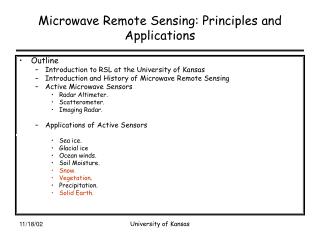
Outline • Introduction • Overview of antenna terminology and antenna parameters • Radiation Pattern • Isotropic, omni-directional, directional • Principal planes • HPBW • Sidelobes • Power Density • Radiation Intensity • Directivity • Beam Solid Angle • Gain and Efficiency • Polarization and Polarization Loss Factor (PLF) • Bandwidth • Antennas as Receivers • Circuit representation of an antenna • Reciprocity • Friis transmission equation O. Kilic EE 543
Outline • Radiation from currents and apertures • Sources of radiation • Current (wire) antennas • Vector and scalar potentail • Short (Hertzian) dipole • Linear antennas • Aperture fields (e.g. horn antennas) • Kirchoff’s scalar diffraction theory • Vector diffraction theory • Array Antennas • Array Factor • Main beam scanning • Endfire antennas • Pattern Multiplication • Directivity calculations O. Kilic EE 543
Summary • So far we have discussed how waves interact with their surrounding in various ways: • Wave equation • Lossy medium • Plane waves, propagation • Reflection and transmission • In this topic we discuss how waves are generated and received by antennas. O. Kilic EE 543
What is an antenna? Antenna is a device capable of transmitting power in free space along a desired direction and vice versa. An antenna acts like a transducer between a guided em wave and a free space wave. O. Kilic EE 543
What is an antenna • Any conductor or dielectric could serve this function but an antenna is designed to radiate (or receive) em energy with directional and polarization properties suitable for the intended application. • An antenna designer is concerned with making this transition as efficient as possible, ensuring as much power as possible is radiated in the desired direction. O. Kilic EE 543
generator Guided em wave Transition region Waves launched into free space Transmission Mode Horn antenna O. Kilic EE 543
detector Receiver Guided em wave Transition region Incident wave Reception Mode O. Kilic EE 543
Antenna Types • Antennas come in various shapes and sizes. • Key parameters of an antenna are its size, shape and the material it is made of. • The dimensions of an antenna is typically in wavelength, l, of the wave it launches. O. Kilic EE 543
Some examples loop Biconal dipole Thin dipole microstrip Parabolic reflector O. Kilic EE 543
Examples: Wire Antennas Wire antennas are used as extensions of ordinary circuits & are most often found in “Lower” frequency applications. They can operate with two terminals in a Balanced configuration like the dipole or with an Unbalanced configuration using a Ground Plane for the other half of the structure. O. Kilic EE 543
Examples: Aperture Antennas Aperture antennas radiate from an opening or from a surface rather than a line and are found at Higher frequencies where wavelengths are Shorter. Aperture antennas often have handfuls of sq. wavelengths of area & are very seldom fractions of a wavelength. O. Kilic EE 543
Examples: Reflector Antennas Reflector antennas collect or transmit (focus) energy by using a large (many wavelength) dish (or parabolic mirror). These are very high gain (directional) antennas used to communicate with or detect objects in space. O. Kilic EE 543
How do these structures launch em energy? • EM energy can be radiated by two types of sources: • Currents: (e.g. dipole, loop antennas. Time varying currents flowing in the conducting wires radiate em energy.) • Aperture fields: (e.g. horn antenna. E and H fields across the aperture serve as the source of the radiated fields.) • Ultimately ALL radiation is due to time varying currents. (E and H fields across the horn aperture is created by the time varying currents on the walls of the horn.) O. Kilic EE 543
E, H J Fundamental Concept of Maxwell’s Equations A current at a point in space induces potential, hence currents at another point far away. V(R) R’ Ri R (0,0,0) rv Charge distribution O. Kilic EE 543
Overview of Antenna Parameters • Radiation Pattern • Radiation Power Density • Radiation Intensity • Directivity • Gain and Efficiency • HPBW • Polarization and Polarization Loss Factor (PLF) • Bandwidth • Beam Solid Angle O. Kilic EE 543
Radiation Pattern (Antenna Pattern) • An antenna pattern describes the directional properties of an antenna at a far away distance from it. • In general the antenna pattern is a plot that displays the strength of the radiated field or power density as a function of direction; i.e. q, j angles. O. Kilic EE 543
Coordinate System O. Kilic EE 543
Solid Angle Solid angle defines a subtended area over a spherical surface divided by R2. Units: Steradians (Sr) For unit solid angle: For unit angle: O. Kilic EE 543
Solid Angle O. Kilic EE 543
Types of Radiation Patterns Idealized Point Radiator Vertical Dipole Radar Dish Omni-directional Directional Isotropic O. Kilic EE 543
Isotropic radiator is a hypotheticallossless antenna with equal radiation in ALL directions. Although it is not realizable, it is used to define other antenna parameters, such as directivity. It is represented by a sphere whose center coincides with the location of the isotropic radiator. q -p p Isotropic Antenna Polar plot Isotropic pattern Rectangular plot O. Kilic EE 543
Directional antennas radiate (or receive) em waves more efficiently in some directions than others. Usually, this term is applied to antennas whose directivity is much higher than that of a half-wavelength dipole. q, j +p -p Directional Antenna O. Kilic EE 543
Omni-directional antennas are special kind of directional antennas having non-directional properties in one plane (e.g. single wire antennas). j -p p Omni-directional Antenna q +p -p O. Kilic EE 543
Principal Planes • E and H planes • Antenna performance is often described in terms of its principal E and H plane patterns. • E-plane – the plane containing the electric field vector and the direction of maximum radiation. • H-plane – the plane containing the magnetic field vector and the direction of maximum radiation. Note that it is usual practice to orient most antennas so that at least one of the principal plane patterns coincide with one of the geometrical planes O. Kilic EE 543
Principal Planes Another definition for principal planes is elevation (q) and azimuth (j) plane. O. Kilic EE 543
Antenna Pattern Lobes A pattern lobe is a portion of the radiation pattern bounded by regions of relatively weak radiation intensity. 0dB Half power beamwidth -3dB Main lobe nulls Full Null Beamwidth Between 1st NULLS Side lobes q +p -p Back lobes PEAK SIDE LOBE LEVEL ( SLL ) ~ -20dB O. Kilic EE 543
HPBW, FNBW O. Kilic EE 543
Field Regions • Close to the antenna, the field patterns change rapidly with distance, and include both radiating energy and reactive energy energy oscillates toward and away from the antenna. • In the near field region non-radiating energy dominates. • Further away, the reactive fields are negligible and only the radiating energy is present. • Sufficiently far away; i.e. far field (Fraunhofer) region field components are orthogonal. The angular distribution of fields and power density are independent of distance. Equipartition between electric and magnetic stored energy. • In between is the transitional, radiating near field region also known as Fresnel region. The angular field distribution is dependent on the distance. • Note that there is no abrupt change in the fields as the boundary between these regions is crossed. O. Kilic EE 543
Reactive near-field region D Far-field (Fraunhofer) Region R>>R2 Radiating near-field (Fresnel) region R1 R2 Field Regions These regions can be categorized as a function of distance R from the antenna. R < R < R1 < O. Kilic EE 543
Radiation Power Density • The time average Poynting vector of the radiated wave is known as the power density of the antenna. Function of q and j. Function of 1/r in the far field O. Kilic EE 543
q -p p Example on Power Density (1) Calculate the total radiated power from an isotropic source. An isotropic source radiates equal power in all directions: The radiated power is the sum of the power density in all directions: So Increasing power with distance??? O. Kilic EE 543
Reiterate isotropic source • An isotropic source radiates equal power in all directions at a given distance form the source. • The distance is in the far field, and the power density is a function of 1/r2 • The power density of an isotropic source is O. Kilic EE 543
Example on Power Density (2) The radiated power density of an antenna is given by Calculate the total radiated power. Solution: 1/2 O. Kilic EE 543
Since will be independent of r decays as 1/r2 in the far field Radiation Intensity • Power radiated from an antenna per solid angle is defined as radiation intensity. • It is a function of q, j only. O. Kilic EE 543
Power Pattern & Radiation Intensity Decays as {1/r2) O. Kilic EE 543
Example on Radiation Intensity (1) Show that the radiation intensity is constant for an isotropic source. Proof: O. Kilic EE 543
Example on Radiation Intensity (2) For an antenna with average power density given by calculate the power density of an equivalent isotropic radiator, which radiates the same amount of power. Solution: From previous example, the total radiated power for this antenna is given as For an isotropic source to radiate the same power as this antenna: So p -p Sav -p p O. Kilic EE 543
Example on Radiation Intensity (3) Calculate the radiation intensity for a Hertzian dipole. O. Kilic EE 543
q, j +p -p Beam Solid Angle • The solid angle, WA, required to radiate all the power of the antenna if the radiation intensity U were uniform and equal to its maximum value within the beam and zero elsewhere. WA WA Umax. WA = Ptot O. Kilic EE 543
Beam Solid Angle Thus the total radiated power is given by Prad = UmaxWA Normalized radiation intensity O. Kilic EE 543
Directivity Directivity is the ratio of the radiation intensity of an antenna in a given direction to the radiation intensity of an equivalent isotropic antenna. O. Kilic EE 543
Directivity • Directivity is a measure of how well antennas direct (focus) energy in one direction. • For an isotropic source, the directivity is 1; i.e. exhibits no preference for a particular direction. • Directivity is typically expressed in dB. • If a direction is not specified, typically the maximum value is implied. O. Kilic EE 543
Directivity Example (1) Show that the directivity of an isotropic source is 1. O. Kilic EE 543
Directivity Example (2) The power density of an antenna is given by Calculate its directivity. Solution: Note that we have solved for the equivalent isotropic source in Example (2) for radiation intensity. Therefore: From the previous solution: O. Kilic EE 543
Directivity Example (3) Calculate the directivity of a Hertzian dipole. O. Kilic EE 543
Pin Prad G Output Input terminal Antenna Gain Gain is the ratio of the radiation intensity in a given direction to the radiation intensity that would be obtained if the power accepted by the antenna were radiated isotropically. O. Kilic EE 543
Gain • Gain is closely related to the directivity. • It accounts for the antenna efficiency as well as the directional capabilities, whereas directivity is only controlled by the antenna pattern. Antenna efficiency Does not involve the input power to the antenna If the antenna has ohmic losses Gain < Directivity. O. Kilic EE 543
Efficiency Accounts for losses associated with the antenna • Sources of Antenna System Loss • losses due to impedance mismatches (reflection) • losses due to the transmission line • conductive and dielectric losses in the antenna • losses due to polarization mismatches reflection dielectric conduction O. Kilic EE 543
Overall Antenna Efficiency The overall antenna efficiency is a coefficient that accounts for all the different losses present in an antenna system. O. Kilic EE 543