Logic Instructions and Programs: Understanding Bit Manipulation in Assembly Language
This chapter introduces essential logic instructions such as ANL, ORL, XRL, and CPL used in bit manipulation for assembly programming. It discusses byte rotation commands like RR, RL, and SWAP, which are crucial for efficient data processing. The section further explores applications of these instructions in converting BCD to ASCII, providing practical examples to illustrate their usage. For comprehensive insights into additional addressing modes and examples, refer to Appendix A.1. Enhance your knowledge of logic operations and their applications in assembly programming.

Logic Instructions and Programs: Understanding Bit Manipulation in Assembly Language
E N D
Presentation Transcript
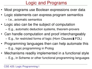
Sections 7.1 Logic and compare instructions 7.2 Rotate and swap instructions 7.3 BCD and ASCII application programs
Objective • 介紹關於邏輯運算的指令。如ANL、ORL、XRL、CPL等指令。另外有執行 byte 旋轉的指令。如RR、RL、SWAP,簡單可是很有用。 • 通常這些指令是用於 bit manipulation,我們關心的只是 byte 中的某幾個 bits 而已。 • 最後有一個範例是利用這些指令做 BCD 與 ASCII 之間的轉換。 • 我們將只是很簡單的介紹這些指令,如果你想得到更多關於這些指令的用法與範例,如更多的 addressing mode 的用法,請看 Appendix A.1。
ANL ANL destination-byte,source-byte MOV A,#35H ;0010 0101 ANL A,#0FH ;0000 1111 => A=0000 0101 • No effect on any of the flags. • ANL is often used to mask (set to 0) certain bits of an operands. AND 2 bits X and Y
Example 7-1 Show the results of the following. MOV A,#35H ;A = 35H ANL A,#0FH ;A = A AND 0FH (now A = 05) Solution: 35H 0 0 1 1 0 1 0 1 0FH 0 0 0 0 1 1 1 1 05H 0 0 0 0 0 1 0 1 35H AND 0FH = 05H
ORL ORL destination-byte,source-byte MOV A,#35H ;0010 0101 ORL A,#0FH ;0000 1111 => A=0010 1111 • No effect on any of the flags. • ORL is often used to set certain bits of an operands to 1. OR 2 bits X and Y
Example 7-2 Show the results of the following. MOV A,#04 ;A = 04 ORL A,#68H ;new A = 6C Solution: 04H 0000 0100 68H 0110 1000 6CH 0110 1100 04 OR 68 = 6CH
XRL ORL destination-byte,source-byte MOV A,#35H ;0010 0101 XRL A,#0FH ;0000 1111 => A=0010 1010 • No effect on any of the flags. • XRL is often used to clear a register, to see if two registers have the same value or to toggle bits of an operands. unchanged toggled XOR 2 bits X and Y
Example 7-3 Show the results of the following. MOV A,#54H XRL A,#78H Solution: 54H 0 1 0 1 0 1 0 0 78H 0 1 1 1 1 0 0 0 2CH 0 0 1 0 1 1 0 0 54H XOR 78H = 2CH
Example 7-4 The XRL instruction can be used to clear the contents of a register by XORing it with itself. Show how “XRL A,A” clears A, assuming that A= 45H. Solution: 45H 01000101 45H01000101 00 00000000 XOR a number with itself = 0
Example 7-5 Read and test P1 to see whether it has the value 45H. If it does, send 99H to P2; otherwise, it stays cleared. Solution: MOV P2,#00 ;clear P2 MOV P1,#0FFH ;make P1 an input port MOV R3,#45H ;R3 = 45H MOV A,P1 ;read p1 XRL A,R3 JNZ EXIT ;jump if A ≠ 0 MOV P2,#99H EXIT: ...
CPL (Complement Accumulator) CPL A MOV A,#55H ;0101 0101 CPL A ;1010 1010 • No effect on any of the flags. • This is also called 1’s complement.
Example 7-6 Find the 2’s complement of the value 85H. Solution: MOV A,#85H ; 85H = 1000 0101 CPL A ;1’s comp. 1’s = 0111 1010 ADD A,#1 ;2’s comp. + 1 0111 1011 = 7BH
CJNE (1/2) • Compare and Jump if Not Equal CJNE destination, source, relative address MOV A,#55H CJNE A,#99H,NEXT ... ;do here if A=99H NEXT: ... ;jump here if A99H • The compare instructions really a subtraction, except that the operands themselves remain unchanged. • Flags are changed according to the execution of the SUBB instruction.
CJNE (2/2) • This instruction affects the carry flag only. CJNE R5,#80,NEXT ... ;do here if R5=80 NEXT: JNC LAR ...;do here if R5>80 LAR: ...;do here if R5<80 Table 7-1
Example 7-7 Examine the following code, then answer the following questions. • Will it jump to NEXT? • What is in A after the CJNE instruction is executed? MOV A,#55H CJNE A,#99H,NEXT ... NEXT: ... Solution: • Yes, it jumps because 55H and 99H are not equal. • A = 55H, its original value before the comparison.
Example 7-8 Write code to determine if register A contains the value 99H. If so, make R1 = FFH; otherwise, make R1 = 0. Solution: MOV R1,#0 ;clear R1 CJNE A,#99H,NEXT ;if A≠99, then jump MOV R1,#0FFH ;if A=99, R1=FFH NEXT:... ;if A≠99, R1=0 OVER:...
Example 7-9 Assume that P1 is an input port connected to a temperature sensor. Write a program to read the temperature and test it for the value 75. According to the test results, place the temperature value into the registers indicated by the following. If T = 75 then A = 75 If T < 75 then R1 = T If T > 75 then R2 = T Solution: MOV P1,#0FFH ;make P1 an input port MOV A,P1 ;read P1 port CJNE A,#75,OVER ;jump if A≠75 SJMP EXIT ;A=75 OVER: JNC NEXT ; MOV R1,A ;A<75, save A R1 SJMP EXIT ; NEXT: MOV R2,A ;A>75, save A in R2 EXIT: ...
Example 7-10 Write a program to monitor P1 continuously for the value 63H. It should get out of the monitoring only if P1 = 63H. Solution: MOV P1,#0FFH ;make P1 an input port HERE:MOV A,P1 ;get P1 CJNE A,#63,HERE ;keep monitoring unless ; P1=63H
Example 7-11 Assume internal RAM memory locations 40H – 44H contain the daily temperature for five days, as shown below. Search to see if any of the values equals 65. If value 65 does exist in the table, give its location to R4; otherwise, make R4 = 0. 40H=(76)41H=(79)42H=(69)43H=(65)44H=(62) Solution: MOV R4,#0 ;R4=0 MOV R0,#40H ;load pointer MOV R2,#05 ;load counter MOV A,#65 ;A=65, value searched for BACK:CJNE A,@R0,NEXT;compare RAM data with 65 MOV R4,R0 ;if 65, save address SJMP EXIT ;and exit NEXT:INC R0 ;increment pointer DJNZ R2,BACK ;keep check until count=0 EXIT ...
MSB LSB RR (Rotate A Right) RR A MOV A,#36H ;A=0011 0110 RR A ;A=0001 1011 RR A ;A=1000 1101 RR A ;A=1100 0110 RR A ;A=0110 0011
RL (Rotate A Left) RL A MOV A,#36H ;A=0011 0110 RL A ;A=0110 1100 RL A ;A=1101 1000 RL A ;A=1011 0001 RL A ;A=0110 0011 MSB LSB
RR (Rotate A Right Through Carry) RRC A MOV A,#36H ;A=0011 0110, CY=0 RRC A ;A=0001 1011, CY=0 RRC A ;A=0000 1101, CY=1 RRC A ;A=1000 0110, CY=1 RRC A ;A=1100 0011, CY=0 MSB LSB CY
MSB LSB CY RLC (Rotate A Left Through Carry) RLC A MOV A,#36H ;A=0011 0110, CY=1 RLC A ;A=0110 1101, CY=0 RLC A ;A=1101 1010, CY=0 RLC A ;A=1011 0100, CY=1 RLC A ;A=1001 1001, CY=1
SWAP A SWAP A MOV A,#72H ;A=72H SWAP A ;A=27H before: before: D7 – D4 D3 – D0 0111 0010 D3 – D0 D7 – D4 0010 0111 after: after:
Example 7-12 (a) Find the contents of register A in the following code. (b) In the absence of a SWAP instruction, how would you exchange the nibbles? Write a simple program to show the process. Solution: (a) MOV A,#72H ;A = 72H SWAP A ;A = 27H (b) MOV A,#72H ;A=0111 0010 RL A ;A=1110 0100 RL A ;A=1100 1001 RL A ;A=1001 0011 RL A ;A=0010 0111
Example 7-13 Write a program that finds the number of 1s in a given byte. Solution: MOV R1,#0 ;R1 keeps the number of 1s MOV R7,#8 ;counter=08 rotate 9 times MOV A,#97H ;find the # of 1s in 97H AGAIN:RLC A ;rotate it through the CY JNC NEXT ;check for CY INC R1 ;if CY=1 then add R1 NEXT: DJZN R7,AGAIN;go through this 8 times
Example Of Serial Communication Write a program to transfer data to serial memories such as serial EEPROMs. Solution: ... RLC A ;first bit to carry MOV P1.3,C ;output carry as data bit RLC A ;second bit to carry MOV P1.3,C ;output carry as data bit RLC A ;first bit to carry MOV P1.3,C ;third carry as data bit ...
Conversion of BCD and ASCII • There is a real time clock (RTC) in many new microcontrollers. • Ex: DS5000T has RTC • RTC keep the time (hour, minute, second) and date (year, month, day) when the power is off. • This data is provided in packed BCD. • For this data to be displayed (ex: on an LCD), it must be in ASCII format. • We show above instructions in the conversion of BCD and ASCII
Packed BCD to ASCII Conversion • To convert packed BCD to ASCII • It must be converted to unpacked BCD first. MOV A,#29H ANL A,#0FH ;get the lower nibble • The unpacked BCD is tagged with 30H ORL A,#30H ;make it an ASCII,A=39H ‘9’
Example 7-14 (modified) Assume that register A has packed BCD, write a program to convert packed BCD to two ASCII numbers and place them in R2 and R6. Solution: MOV A,#29H ;packed BCD ANL A,#0FH ;Lower nibble: A=09H ORL A,#30H ;make it an ASCII, A=39H (‘9’) MOV R6,A ;R6=39H ASCII char MOV A,#29H ; ANL A,#0F0H ;upper nibble: A=20H SWAP A ;A=02H, equals to ”RR A” 4 times ORL A,#30H ;A=32H,ASCII char.’2’ MOV R2,A ;R2=32H ASCII char
ASCII to packed BCD Conversion • To convert ASCII to packed BCD • It must be converted to unpacked BCD first. MOV A,#’2’ ;A=32H ANL A,#0FH ;get the lower nibble MOV R1,#’9’ ;R1=39H ANL R1,#0FH ;get the lower nibble • Combined them to the packed BCD. SWAP A ;become upper nibble A=20H ORL A,R1 ;packed BCD,A=29H
You are able to • Define the truth tables for logic functions AND, OR, XOR • Code 8051 Assembly language logic function instructions • Use 8051 logic instructions for bit manipulation • Use compare and jump instructions for program control • Code 8051 rotate and swap instructions • Code 8051 programs for ASCII and BCD data conversion
Homework • Chapter 7 Problems:4,5,10,11,14,15 • Note: • Please write and compile the program of Problems 10,11,14,15