
In this presentation you will :
In this presentation you will : identify how gears can be used to change the axis of rotation in a mechanism. In this presentation you will discover the different types of gears that are used to change the axis of rotation in a mechanical system.

In this presentation you will :
E N D
Presentation Transcript
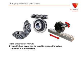
In this presentation you will: • identify how gears can be used to change the axis of rotation in a mechanism
In this presentation you will discover the different types of gears that are used to change the axis of rotation in a mechanical system. You will see different types of bevel gears and identify where they are most likely to be used. You will also see how rack-and-pinion and worm gears operate. Next >
Bevel Gears Bevel gears are primarily used to transfer power between intersecting shafts, where the axis of rotation of two shafts are at 90 degrees to each other. The teeth of these gears are formed on a conical surface. Next >
Apex of the cone Types of Bevel Gears Standard bevel gears have teeth that are cut straight. The teeth point toward the apex of the cone on which they are machined. Next >
Spiral bevel gears have teeth that have been cut on a curve. The larger surface contact area makes for a smoother, quieter running system, much like helical gears. Next >
Parallel shafts Intersecting shafts Hypoid bevel gears are a special type of spiral gear that will allow non-intersecting, non-parallel shafts to mesh. Hypoid gears are stronger, operate more quietly, and can be used for higher reduction ratios than spiral bevel gears. Next >
Question 1 Bevel gears are primarily used to transfer power between parallel shafts. Is this true or false? Answer True or False.
Bevel Gear Applications Standard bevel gears are mainly used in low speed (less than 500 rpm) applications. At high speeds they become noisy. They are typically used in applications such as hand drills. Spiral bevel gears are typically used for high speed (greater than 500 rpm) and performance applications, where low noise and vibration levels are important. They are typically used in transmission systems. Hypoid bevel gears are also used in high performance applications, but are more expensive to produce. They are typically used in transmission systems. Next >
Question 2 Which type of bevel gear is typically used in low speed applications? A) Standard B) Spiral C) Hypoid
Worm gears Helical gears Spur gears Worm Gears Worm gears resemble screws, and can be used to drive gear wheels (spur gears or helical gears). They allow two non-intersecting shafts at right angles to mesh with each other. Worm drives provide a large reduction in speed. For one rotation of the worm gear, the gear wheel moves by a distance of one tooth. They are typically used in gearboxes, where large reductions in speed, for example 300:1, are required. Next >
Question 3 A worm gear is driving a gear wheel that has 20 teeth. How far will the gear wheel turn, if the worm gear rotates 5 times? Enter your answer in degrees. Enter your answer and press SEND.
Pinion gear Rack gear Rack-and-pinion Gears The rack-and-pinion is typically used to turn rotary motion into linear (straight line) motion, or vice versa. Racks are simply straight gears. The pinion is usually a spur gear that meshes with the rack. As the pinion turns, the rack moves in a lateral direction. The rack-and-pinion is typically used in automotive steering systems. Next >
Question 4 The rack-and-pinion is typically used in automotive steering systems, and converts rotary motion into linear motion. Is this true or false? Answer True or False.
Number of Driven Gear Teeth Gear ratio = Number of Driver Gear Teeth ˙ 100 Ratio = = 1.6:1 60 90 = 90:1 1 Gear Ratios Driven The gear ratio of a bevel gear system is calculated in the same way as for a simple gear train. Driver With a worm system, the worm gear is equivalent to a single tooth gear. If the spur gear has 90 teeth, then the gear ratio is: Next >
Summary You should now be aware of: • which types of gear can change the axis of rotation in a mechanism • how to calculate gear ratios for bevel gears and worm gear systems End >