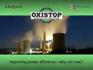
Improving power efficiency—why not now?
Improving power efficiency—why not now? . welcome and thank you. Energy Efficiency: Improving Power Efficiency Improving Power Efficiency—Why Not Now? Oxistop LLC Youngstown State University Sustainable Energy Forum June 8, 2010. presentation objectives. Defining the opportunity

Improving power efficiency—why not now?
E N D
Presentation Transcript
welcome and thank you Energy Efficiency: Improving Power Efficiency Improving Power Efficiency—Why Not Now? Oxistop LLC Youngstown State University Sustainable Energy Forum June 8, 2010
presentation objectives • Defining the opportunity • Introduction of the existing technologies • Benefits of the existing technologies • Recognizing obstacles • Overcoming obstacles
energy efficiency and conservation Economic Realities Current economic realities have forced the Power Utility Industry and America's Heavy Industries to use what was considered by them to be discretionary dollars as a means of maintaining basic operations, leaving little money or incentive for investing in new technologies for efficient power generation development.
Improving power efficiency—why not now? “It's hard to remember now. But before Congress got all bogged down with healthcare reform last summer, the House had passed a major piece of energy and climate legislation that would have capped greenhouse gas emissions and put billions into renewable energy and new technologies...” K.G. U.S. News & World Report, Summer 2010
energy efficiency and conservation Ceramic Coatings And Magnetic Field Technologies Technologies exist today that are proven solutions in other industries for problems associated with energy efficiency and energy conservation issues and have existed for many years.
energy efficiency and conservation Why Are The Technologies Not Being Used In The Power Utility Industry? • No real economic incentive to change current practices • New to the Power Utility Industry, where they are considered experimental • Not fully validated and tested by the Power Utility Industry
energy efficiency and conservation Ceramic Coatings And Magnetic Fields What Are Some Of These Technologies? • High emissivity Ceramic coatings for energy enhancement • Low emissivity Ceramic coatings for energy conservation • Magnetic Field Units (MFU), conservation of finite natural resources for fuel and water treatment technologies
high emissivity ceramic coatings Ceramic boiler tube coatings improve power generation and reliability of the boiler while reducing emissions. • improving fuel efficiencies in various industries • reducing slag and residue buildup • resisting corrosion and erosion • preventing oxidation of boiler tubes ALL CRITICAL TO EFFICIENCY AND AVAILABILITY OF POWER GENERATION EQUIPMENT
slag challenges & coating solutions Slag buildup creates many problems, including loss in boiler efficiency, potentially damage to the unit and danger to personnel from falling slag. Procera™ Coating Base metal Oak Ridge National Laboratory U. S. Department of Energy Slag buildup on uncoated tube wall Slag that has shed off the ceramic coated tube wall Magnification of ceramic coating bond with carbon steel substrate
corrosion challenges & coating solutions Challenges: Oxidizing High Sulfur Conditions sulfides tube metal slag furnace gas (pyrite) oxide sulfide corrosion
corrosion challenges & coating solutions Solution: Ceramic Coatings—Protective Layer Procera™ MC19-GRP—Protective Layer Ceramic Coating provide a “protective layer,” through complete chemical and mechanical bonding to the tube’s surface tube metal slag furnace gas (pyrite) Ceramic Coating
AEP ceramic coating case study (how does this work) American Electric Power Picway Power Plant (2004-2005)
AEP ceramic coating case study First Installation. Trial area around burners to stop slag buildup Before coating install, burner with upper eyebrow Trial burner grit blast surface preparation Trial burners with ceramic coating applied
AEP ceramic coating case study Technology is verified in the field Before coating install, uncoated with eyebrow Coated burner wall, note excellent flame profile Slag shedding off burner wall coated with ceramic coating
NRG ceramic coating case study Huntley’s expectations of the coatings • coating will lessen the thermal shock and damage to tubing overall heat absorption in the furnace will improve cost of application is below that of other corrosion coating options • NRG Energy Inc Huntley Power Plant (2006-2007) •
NRG ceramic coating case study payback for the cost…24 DAYS Results • lower furnace exit gas temperatures (FEGT) as a result of greater absorption lower fuel (coal) usage eliminating over firing to make steaming rate maximum megawatt output is increased to full load of 198 Megawatts, with slightly less coal burned • •
AECI ceramic coating case study Associated Electric Cooperative Inc New Madrid Power Plant (April, 2008)
ash fowling before coatings • NEW MADRID POWER PLANT CHALLENGES: • ash fowling control of inlet and outlets of secondary superheater (SSH) • slag bridging across front of SSH • improving fuel efficiencies and heat absorption by reducing slag
Uncoated next to coated, after 6 months online, un-cleaned
New Madrid’s coating observations Economizer Outlet Flue Gas Temperature • no bridging across front of SSH SSH fouling rate approximately half of historic rate coating visible In some areas and overall condition appears very good higher heat absorption rate • • U1 Current Run (Oxistop, 2008) U1 Summer, 2007 (Control) U1 Average Summer, 2004 – Winter, 2006–2007 •
coating application areas (a comprehensive approach) Boiler Bank Superheater Combustion Chamber Hot Cyclone Collector Economizer Air Heater Dust Collector ID Fan High emissivity coatings for energy enhancement (Production Side) Low emissivity coatings for energy conservation (Conservation Side)
low emissivity ceramic coatings Ceramic thermal insulating coatings for energy conservation that reduce energy cost and provide emission control. • excellent thermal insulation at low thicknesses • eliminates Corrosion Under Insulation (CUI) • easy application to irregular surfaces • excellent personnel protection conventional insulation
low emissivity ceramic coatings What is the difference between conventional insulation and Thermal Insulation Coatings (TIC). conventional insulation thermal insulation coatings • CUI • Difficult Repairs • Maintenance • Wear/Vibration • No Inspect Ability • Limited Protection • No More CUI • Easy Repairs/Touch Ups • No Regular Maintenance • Virtually No Wear • Total Inspect Ability • Constant Substrate Protection Job was expedited by Hurricanes Katrina & Rita
thermal insulation coating (TIC) ceramic coating case study I Diffuser • Sugar mill diffuser was not cost effective to conventionally insulate Coating was selected due to its rapid application as well as total service ability Post application all of its sugar mill process was well within the design parameters and allowed the facility to save tremendous dollars on energy • Substrate: Diffuser (sugar mill) Problem: CUI, Personnel Protection, Heat Retention Reason: Needed to keep diffuser at steady temp and protect personnel from burns Starting Temp = 190°F (87°C) Post app. Temp = 110°F (43°C) DFT = 60 mils •
thermal insulation coating (TIC) ceramic coating case study II Shell Heat Exchanger • Unit had a process temperature requirements starting at 200F and tapering to 100 F. The coating allowed the facility to save costs of total insulation as the application could be tailor-sprayed to temperature requirements. Use of DTI brought the goal of Personnel Protection well with their limits and eliminated CUI. Substrate: Shell Heat Exchanger Problem: CUI, Personnel Protection, Reason: Ease of maintenance, personnel protection Starting Temp = 200°F (93°C) Post app. Temp = 110°F (43°C) DFT = 40-60 mils (1.0-1.5mm) •
coatings for energy conservation (commercial applications) How Do The Coatings Work?
water treatment Magnetic Field Units (MFU), conservation of finite natural resources for fuel and water treatment technologies. • No energy required to operate • Has no parts subject to wear and no • moving parts (No maintenance) • Greatly reducing of chemical expenses associated with water treatment • Magnet system is a permanent solution to water treatment issues, giving immediate benefit • Life and effectiveness of the system with match the operating equipment
water treatment Cooling Water Systems and Boiler Efficiencies Magnetic Field Units for water replace the cost of chemicals and maintenance cleanings by applying a safe, permanent, cathodicprotection voltage to cooling process liquids. The MFU aggressively removes hard scale, deposits, and bio-fouling that can reduce or eliminate waterside related maintenance outages.
water treatment Cooling Water Systems and Boiler Efficiencies Cooling towers and condensers can create a back pressure within the turbine if the system’s efficiency is compromised by calcium carbonate build up and organic matter accumulation. The traditional way to treat this occurrence is to treat the system with chemicals to deal with the various issues—a costly balancing act never 100% effective, and scheduled cleanings are required and a certain amount of back-pressure is tolerated.
Birchwood 9% Case Study 9% Increase In Power Output Reported With HYDROLATOR™ • 9% increase, to reach designed capacity (output reached 256 MW) • 20 MW additional production (Historically, this plant's peak output never exceeded 236 MW) • No condenser cleaning was required after increased power output and installation—$300,000/yr savings in chemical treatment expenses • $7 million/yr profit as a result of increased power output and HYDROLATOR’s permanent cleaning • HYDROLATOR equipment has been utilized since 2000 with consistent performance results
fuel conservation MFU for conservation for fuel: MAXSYS FUEL SYSTEMS • In-line magnetic fuel treatment system (minimum 5% fuel savings assured) • Pre-treat gas and oil prior to combustion to enhance combustion efficiency while lowering emissions • Retrofit system - no power or maintenance required • No interference to the process and combustion plant • Does not affect burning equipment warranty • Compatible with all burners across a range of industries
pushing and pulling strategies effect energy flow Can Power Efficiency Be Improved Today? YES IT CAN! BY “PUSHING” WITH CERAMIC COATINGS AND “PULLING” WITH MAGNETIC FIELD TECHNOLOGIES TO CREATE NEW ENERGY FLOW DYNAMICS WHAT DOES THIS MEAN…
pushing and pulling energy flow Push And Pull Strategies For More Efficient Power Generation And Increased Revenue Income
recognizing obstacles Inherent problems are that vested interest groups are against new technologies for energy efficiency and conservation because: • the “why fix what is not broke” • owners and operators are “set in their ways” (stay the course) or feel that their job security is at risk. • in many cases, fuel costs are passed-on to the end consumer. • boiler manufacturers’ answer is to “simply build a bigger box [boiler].” • owners have vested interests in traditional technologies; such as chemicals; different boiler and burner designs; or other tube coating technologies such as weld overlay and thermal (metal) spray.
overcoming obstacles Additional Funding (Grants) And Real Incentives For: $ For Funding – RESEARCH AND VALIDATION, such as education institutions and testing and research facilities such as Babcock & Wilcox Company Research Center (BWRC) in Barberton, Ohio. $ For Funding – FIELD TRIALS with “End Users”—Heavy Industry and Power Generation (Companies that would benefit by use of these Technologies) $ To Provide Funding – For companies that specialize in promoting new technologies that are dedicated to energy efficiency and conservation.
Improving power efficiency— why not now! Today’s use of these technologies can be the bridge to our future evolution in efficient production and conversation of our energy resources. Tim Batton, President Oxistop LLC • Salem Energy Solutions • Sáetech LLC Phone: 330-332-1111 • Cell: 330-885-0902 1413 Quaker Circle, Salem Industrial Park • Salem, Ohio 44460 • www.oxistopllc.com