Next-Gen Glass Etching System - Innovative 3-D Laser Technology
460 likes | 491 Vues
Join Group 20's advanced team in developing a cutting-edge glass etching system, aiming to revolutionize award production with improved user-friendliness and safety. Featuring new automation, enhanced image processing, and precision engineering.

Next-Gen Glass Etching System - Innovative 3-D Laser Technology
E N D
Presentation Transcript
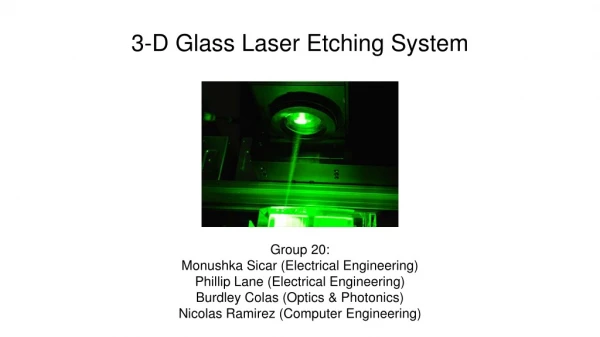
3-D Glass Laser Etching System Group 20: Monushka Sicar (Electrical Engineering) Phillip Lane (Electrical Engineering) Burdley Colas (Optics & Photonics) Nicolas Ramirez (Computer Engineering)
Motivation Old Etching System: • Make 6 Awards at the same time • Not User friendly • Defect in image rendering • Hazardous (Electrical & Optical) • Long lead time • Bulky in size
Goals and Objectives • Etch a single glass at once • Improvements user friendliness • Automate image formatting and processing • Eliminate need for machine pre-orientation • Higher safety standards • Integrate drivers as part of the machine • Protective optical shielding around machine
Specifications and Requirements • Minimum glass size: 2.75 x 2.75 x 2.75 cubic inches • Max dimensions: • Total surface Area: 3 feet x 3 feet • Moving Parts: 2 feet x 2 feet surface area, 3 feet height • Move up to 20 lb. payload in vertical and horizontal direction • Use serial communications for real time control • Decrease etching time by 40% based on standard image (Pegasus logo) • Image Resolution 167 x 167 x 167 pixels for a 1 inch x 1 inch x 1 inch dimension (UCF Pegasus Logo)
Overall System Diagram Power Comms and Control Movement Mechanisms and Payload Optics Main Supply U.S. Standard (110-120 VAC) AC/DC Adaptor (12 VDC) Regulator (5VDC) ATmega 328P MCU Axis Limit Switches Motor Driver Supply (18 - 80 VDC) Stepper Motor Drivers FT232RL USB-to-Serial Optics Laser Stepper Motors Optical Assembly Z-Axis Mount Etching Glass X and Y Surface Mount
Overall System Diagram Power Comms and Control Movement Mechanisms and Payload Optics Main Supply U.S. Standard (110-120 VAC) AC/DC Adaptor (12 VDC) Regulator (5VDC) ATmega 328P MCU Axis Limit Switches Motor Driver Supply (18 - 80 VDC) Stepper Motor Drivers FT232RL USB-to-Serial Optics Laser Stepper Motors Optical Assembly Z-Axis Mount Etching Glass X and Y Surface Mount
Power • Constraint: using laser source from old machine • Various operating voltages • Laser Source: 115 VAC • Motor Drivers: 18-80 VDC • MCU: 5 VDC
Power Consumption (Runtime) G201X DigitalStep DriveGeckoDrive • Voltage Rating: 18- 80 VDC • Power Rating: 1- 13 Watts Nema 23-BipolarStepperOnline(340 oz-in) • Voltage Rating: 24- 48 VDC ( Using 36 VDC) • Current Rating: 1.8 A/ phase
AC/DC Adapter • All of the electronics comprising the 3-D Laser Etching System, except the laser unit, motors, and motor drivers, are operated on direct current (DC) power • Power needs to converted to DC for the low voltage components ie. (Microcontroller), as well as provide a constant output voltage
Regulation • Supplies 5 VDC to MCU • Heat sinking a non-issue due to low current consumption • Efficiency a non-issue due to low current output
Overall System Diagram Power Commands and control Movement Mechanisms and Payload Optics Main Supply U.S. Standard (110-120 VAC) AC/DC Adaptor (12 VDC) Regulator (5VDC) ATmega 328P MCU Axis Limit Switches Motor Driver Supply (18 - 80 VDC) Stepper Motor Drivers FT232RL USB-to-Serial Optics Laser Stepper Motors Optical Assembly Z-Axis Mount Etching Glass X and Y Surface Mount
FT232 IC Purpose • USB-to-Serial Conversion • Programming MCU • Gcode streaming
MCU Selection Selection Criteria • Serial communication • ≥ 10 I/O Pins • Current consumption • Memory • Cost
MCU Firmware Critical System Needs • Concurrent control of 3 motors • Line (Bresenham), cornering, and arc algorithms • User friendly • Real-time start/stop • Steps/distance specification • Travel limit specifications • Open source • Homing and Localization
Grbl High Level Diagram Start Homing Buffer Full? NO YES Wait for Command to Clear Read Command Parse Command Command Cleared Accept Command Velocity & Acceleration Planner GCode Buffer Execute Command Clear Command
Axis Limit Switches Purposes • Limit travel during etching process • Normally open configuration • Grbl homing feature
Overall System Diagram Power Movement Mechanisms and Payload Comms and Control Optics Main Supply U.S. Standard (110-120 VAC) AC/DC Adaptor (12 VDC) Regulator (5VDC) ATmega 328P MCU Axis Limit Switches Motor Driver Supply (18 - 80 VDC) Stepper Motor Drivers FT232RL USB-to-Serial Optics Laser Stepper Motors Optical Assembly Z-Axis Mount Etching Glass X and Y Surface Mount
Software Design Programming Language • Python 3 • Extensive standard library • Easy to implement Libraries • TkInter • pySerial Operating System • Windows 10
Simplified Flow User Input 2D - 3D Conversion Etching
Example Conversion JPG/PNG File BMP SVG STL
Slicer Slicing • STL object is “cut” into slices • G-code file output • Slic3r G-code • Numerical Control Language • Standard in CAM tools and machines • Movements • Where to, how fast, what path Example G-code: G02 X5 Y10 Z5 R10
G-code Streaming Python Script • Pyserial module • Python Standard Library RS-232 Interface • Serial communications interface • Laser control before streaming USB • Microcontroller communications • G-code transmission
User Interface TkInter Module • Python Standard Library • Layer over Tcl/Tk Toolkit • Object Oriented Major Focuses of UI • Automation • Simplicity • Unification
User Interface Design Image Preview STL Slicing and G-code Generation Area Etching and Laser control Area
Overall System Diagram Power Movement Mechanisms and Payload Comms and Control Optics Main Supply U.S. Standard (110-120 VAC) AC/DC Adaptor (12 VDC) Regulator (5VDC) ATmega 328P MCU Axis Limit Switches Motor Driver Supply (18 - 80 VDC) Stepper Motor Drivers FT232RL USB-to-Serial Optics Laser Stepper Motors Optical Assembly Z-Axis Mount Etching Glass X and Y Surface Mount
Laser: Type: Nd-YAG Wavelength: 532 nm Energy : 30 mJ Repetition Rate Frequency: 20 Hz Pulse Width: 10 ns • Q-Switched • Pulsed • Water Cooled • Flashlamp Pumped Laser Operation: • Turn Key • Adjust Desired Energy level • Adjust Repetition Rate Frequency • Push Q-Switch • Push Start
Beam Expansion and Subsequent Focusing Lens Zemax Simmulation: • A telescoping beam expansion is implemented in the system to increase the diameter of the beam • A focusing lens is inserted to focus the beam to the desired beam spot to etch in the glass. Lens Parameters and Spot Diagram : • Lens 1: focal length of -12 mm, and a diameter of 12 mm • Lens 2: focal length of 25.4 mm, and a diameter of 25.4 mm • Lens 3: focal length of 50 mm, and a diameter of 25 mm • Beam spot 3 microns diameter
Optical System Design PREVIOUS SYSTEM DESIGN: • This design intended to copy the old system design. • Using a two layer approach, the system has the z-axis which take the laser beam from above to etch the glass. • The advantages of the old system design helped us save on mechanical parts
Optical System Design CURRENT SYSTEM DESIGN: • Eliminates potential of extra mirrors due to axis change in beam optical path. • The Polarizer and Half Wave Plate are set in front of to the beam expansion and the focusing lens to help with beam clipping • The z-axis will now move the focusing lens, the xy-axis will move the glass • Safety : System will be surrounded by a Shield preventing hazard from reflected laser beam.
Testing Laser: • With the currently working laser, a system was set in place to damage the glass. • The concept was a proof of our laser is suitable for our project success.
Image Resolution: Our Image to etch is the UCF Pegasus Logo: Dimension: 1 inch x 1 inch x 1 inch Giving a resolution of : 167 x 167 x 167 pixels With a beam spot size of 3 um.
Overall System Diagram Power Movement Mechanisms and Payload Comms and Control Optics Main Supply U.S. Standard (110-120 VAC) AC/DC Adaptor (12 VDC) Regulator (5VDC) ATmega 328P MCU Axis Limit Switches Motor Driver Supply (18 - 80 VDC) Stepper Motor Drivers FT232RL USB-to-Serial Optics Laser Stepper Motors Optical Assembly Z-Axis Mount Etching Glass X and Y Surface Mount
XY-Axis Post & Z-Axis Post: XY-Linear Stage: Holding the glass to be etched Z- Stage: Holding Focusing Lens
Next Steps Software Development • Complete user interface • Configure grbl firmware for etching Hardware Development • PCB soldering • Wiring: PCB to drivers and switches Framework & Optics Development • XY stage • Mount motors and etching glass to stage • Mount stage to optics table • Z-axis • Mount focusing lenses • Mount vertical post to optics table
Success / Issues • Electrical Engineer • S: Components have been successfully working • I: Designing of the PCB • I: Status of orders • Computer Engineer • S: Sufficient Progress in GUI • I: Incomplete testing of slicing/G-code • I: Incomplete testing of RS232 laser control • Optics and Photonics Science and Engineering • I: Laser functionality • S: Etching into glass
Thanking Our Sponsor Dr. MJ Soileau