Using MVSIS for Language Equation Solving
190 likes | 213 Vues
Explore how to solve language equations using Multi-Valued Networks in MVSIS, with insights on various input formats and optimization procedures. Learn about FSMs, sequential circuits, and more.

Using MVSIS for Language Equation Solving
E N D
Presentation Transcript
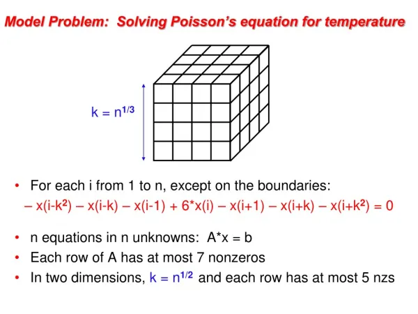
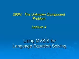
Using MVSIS for Language Equation Solving 290N: The Unknown Component Problem Lecture 4
Overview • MVSIS • Multi-valued networks • MVSIS input formats • Binary functions and networks (PLA, BLIF) • Multi-valued functions and networks (BLIF-MV) • FSMs and finite automata (three options) • Using BLIF/BLIF-MV followed by “stg_extract” • Using modified KISS2 format • Using modified BLIF-MV format • Demo
MVSIS • New logic synthesis system (2001-2004) • A successor of SIS (1987-1992) • More general algorithms, improved implementation • Additional capabilities to work with multi-valued networks • Optimization procedures using complete flexibility • Minimization of multi-valued relations • Windowing • Additional capabilities to work with sequential objects • Sequential circuits (sweeping, extracting sequential DCs, extracting STGs) • FSMs and automata (language equation solving procedures)
MVSIS • Credits • Robert Brayton, inspiration, guidance, ideas, testing, … • William Jiang, worked on early versions, developed “fullsimp”, “club”, “cvr” packages, supported the code • Roland Jiang, worked on early versions, developed the encoding package • Yinghua Li, worked on early versions, developed “pair_decode” package and code for asynchronous synthesis • Donald Chai, worked on early versions, advice on programming, data structures, naming APIs • Satrajit Chatterjee, contributed a layout-aware logic extraction package, advice on programming, data structures, supporting the code
Multi-Valued Networks • Multi-valued networks are more general, compared to binary • A node may have more than two values • A latch may have more than two values • A node can be incompletely-specified • A node can be non-deterministic Completely-specified Incompletely-specified Non-deterministic
MVSIS Input Formats • Binary functions and networks • PLA, BLIF • Multi-valued functions and networks • PLA-MV, BLIF-MV • FSMs and finite automata • (as networks) BLIF, BLIF-MV • (as binary STGs) Modified KISS2 • (as MV STGs) Modified BLIF-MV (under construction)
Cube Representation of a Function F = ab + c’d Cube table for variable order (a,b,c,d) 11-- 1 --01 1 Cube table for variable order (a,c,b,d) 1-1- 1 -0-1 1
PLA Format .i <number of inputs> .o <number of outputs> .ilb <list of input names> .ob <list of output names> .p <number of product terms> <cube representation of the function> .e
Example of a PLA file .i 4 .o 1 .ilb a b c d .ob F .p 2 11-- 1 --01 1 .e
BLIF Format .model <you name it> .inputs <list of input names> .outputs <list of output names> .names <list of fanin names> <node_name> <PLA representation of the node’s function> .names <list of fanin names> <node_name> <PLA representation of the node’s function> … .latch <latch_input> <latch_output> <reset_value> .latch <latch_input> <latch_output> <reset_value> … .end
w x z DFF y Example of a BLIF file .model example .inputs x y .outputs z .names x y w 11 1 .latch w z 0 .end
BLIF-MV Format • Differences compared to BLIF: .mv <var name> <number of values> <list of value names> Gives the values of the MV variable (optional for binary variables) .default <value> Gives the default value of the MV node .reset <latch_output> Gives the reset value (function) of the latch. .table (synonym of .names) Changes to the MV table representation: • the literals are separated by spaces, • multi-valued literal can be represented as a set of values, for example, (2,3,5) or as interval of values, for example, {3-5} • the “=“ constructs can be used to compactly specify multiplexers
w x z DFF y Example of a BLIF-MV file BLIF BLIF-MV .model example .inputs x y .outputs z .mv x 2 .mv y 2 .mv z 2 .mv w 2 .table x y w .default 0 1 1 1 .latch w z .reset z 0 .end .model example .inputs x y .outputs z .names x y w 11 1 .latch w z 0 .end
Inputting Automata into MVSIS • Read in BLIF/BLIF-MV network and extract its STG (command “stg_extract”) • Use the modified KISS2 format • Use the modified BLIF-MV format (under construction)
110 000 010100 111 001 011101 0 1 w x z DFF y Extracting STG from the network .model example .inputs x y .outputs z .names x y w 11 1 .latch w z 0 .end
Modified KISS format .i <number of inputs> .o <number of outputs> (zero, for automata) .ilb <list of input names> .ob <list of output names> .p <number of product terms> .s <number of states> .accepting <list of accepting states> <cube cover of the condition> <cur state> <next state> <cube cover of the condition> <cur state> <next state> … .e
Example of a KISS2 file .i 2 .o 0 .s 3 .p 7 .ilb i o .ob .accepting a b 11 a a 00 a b 10 a DC 01 a DC -1 b a -0 b DC -- DC DC .e
Modified BLIF-MV format • An automaton is represented as an MV network with two nodes and one latch: • The next-state node • depends on the inputs and the current state • can be non-deterministic if the automaton is non-deterministic • The binary output node • depends on the current state only • produces output 1 iff the state is accepting • The latch • represents the relationship between the current state and the next state variables • The only additional directive (.fsm) • specifies what inputs of the automaton are inputs/outputs of the underlying FSM (if applicable)
Example of a BLIF-MV file .i 2 .o 0 .s 3 .p 7 .ilb i o .ob .accepting a b 11 a a 00 a b 10 a DC 01 a DC -1 b a -0 b DC -- DC DC .e .model automaton .inputs i o .outputs ACCEPT .fsm i -> o .mv CS, NS 3 a b DC .table cs ACCEPT .default 0 (a,b) 1 .table i o CS NS .default DC 1 1 a a 0 0 a b - 1 b a .latch NS CS .reset CS a .end