SPS Beam Dump System Issues and Solutions
200 likes | 234 Vues
Discusses problems with SPS beam dumping system in 2006, including vacuum interlock issues and beam dump block outgassing. Presents history and solutions for the TIDVG vacuum problem. Explores long-term solutions and considerations for system improvement.

SPS Beam Dump System Issues and Solutions
E N D
Presentation Transcript
The SPS Beam Dump Jan Uythoven (AB/BT) Thanks to: Y. Kadi, M. Owen, G. Vossenberg, E. Carlier, L. Ducimetière, K. Cornelis
SPS Beam Dumping System • Problems with the SPS Beam Dumping System during operation in 2006: • Outgassing of the beam dump block TIDVG when large beam intensities are dumped on the block • Leading to vacuum interlock of the injection system MKP situated next to it • Vertical dump kicker MKDV HV break down • Required time to recondition • Possible damage to the machine • This talk • More detailed description of the problems • Possible cures of these problems and actions to take for the future ATC/ABOC days, 23 January 2007
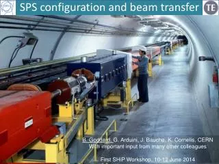
Beam Dumping System LayoutView in the Vertical Plane QDA1191 QFA1181 QDA1171 3 x MKDH MKDV1, MKDV2 MKP TIDH MDSH TIDV TBSJB ATC/ABOC days, 23 January 2007
TIDVG ATC/ABOC days, 23 January 2007
History on the High Energy Beam Dump TIDVG • ~ 10 years ago TIDV magnet with water cooled Al / CU core • No degassing because different surface material and core well cooled • Small cracks in water cooling system spoiling the vacuum • Replaced by first TIDVG with graphite core and Ti foil • Ti foil on top of core to prevent graphite particles to ‘float’ towards the MKP just next to it • Carefully conditioned with the beam after installation • Couple of weeks dedicated work in parallel with machine set-up • Foil damaged (hit in case of asynchronous dump), leading to ‘soft aperture restriction’ • Replaced 2006 run with TIDVG without foil • ‘Bake-out’ in situ with warm water under pressure (150 °C) • Vacuum problems during 2006 run -> • Spare (=third) TIDVG soon at workshop in March to remove Ti foil + ?? ATC/ABOC days, 23 January 2007
Vacuum behaviour during CNGS operation IL level ATC/ABOC days, 23 January 2007
Problems during 2006 Run • CNGS operation • High intensity beam not extracted because of extraction inhibit (most critical: position of the extracted beam, variations with beam intensity) • ‘Couple’ of full intensity beams (3e13) dumped on the TIDVG caused the vacuum of the adjacent injection kickers MKP > 1·10-6 mbar; injection interlock • Impact on operation reduced towards the end of the 2006 run by creating an injection inhibit when 4 x extractions ‘stopped’ • Had to be changed for new super cycle with 3 CNGS cycles = 6 CNGS extractions • Reset counter for injection inhibit by super cycle with all beams properly extracted • Not a solution for high intensity MDs when beam should not be extracted ATC/ABOC days, 23 January 2007
Problems during 2006 Run • LHC operation • High Intensity LHC beam, being dumped, also causes the vacuum of the injection kickers MKP > 1·10-6 mbar, injection interlock • Problem during MDs and later for set-up of high intensity LHC beams Operation with 5 batches of 48 bunches @ 80 % nominal intensity (=2.1e13): IL ATC/ABOC days, 23 January 2007
.. but with LHC beams Two peaks at same time as on previous slide Vacuum also going up to Interlock Level at the extraction kickers in 6 at the same time. Peak around 1e-6 mbar as well! “electron cloud”? and/or outgassing ATC/ABOC days, 23 January 2007
Solutions TIDVG Vacuum Problem • Conditioning with beam • Conditions by increasing temperature and ‘shocks’ • Needs beam time • But probably well on the way with the present beam dump • Would be nice to quantify (dp versus intensity dumped) • Disadvantage: Needs to be done again when dump replaced • In situ bake-out of present system • No conditioning by ‘shocks’ (KC) • Not clear if possible, big mass: likely to need some modifications (YK) • Not clear which temperatures are required: waiting test results on sample AT/VAC • Not clear if possible with the quick disconnects (KW) • Bake-out of third (spare) TIDVG and to be installed later • Need installation under vacuum which would require several modifications: valves and ‘mires’ for alignment to be added to the system • Some other mechanical modifications to allow bake-out • By that time presently installed TIDVG probably already conditioned by beam • But would take away problem in case of replacement ATC/ABOC days, 23 January 2007
Longer Term Solutions? • Has been mentioned to displace beam dumping system to different LSS • Study Claudio Arimatea, 1998: • Expensive (685 k for the kickers only at that moment) and time consuming • Would make a clean area radioactive • Interesting in 1998 for the construction of the ‘new’ dump • Present Beam Dumping System • In principle works well • Only need to condition / solve outgassing • Does not seem to behave very different from installation ~ 10 years ago • Good to have dump as limiting vertical aperture during normal operation • Only real unknown is the possible contamination of the injection kickers MKP by ‘TIDVG graphite dust’ • Problem not confirmed, but could be very annoying ATC/ABOC days, 23 January 2007
SPS Beam Dump KickersOperation with Reduced Voltage • Vertical SPS Beam Dump Kicker, MKDV1, high voltage problem in 2006 • Spark = breakdown to earth about 1x per week with ‘nominal’ operation voltage • HV feedthrough MKDV1 changed beginning of 2006, see photo’s -> • After approval ABOC October 2006: operational voltage MKDV1 and MKDV2 reduced to 40 kV • Since then no breakdowns any more • Reduced protection in case of ‘sweep’ or breakdown • But protection already limited because MKDV1 and MKDV2 are physically linked, does not get much worse by lowering the voltage ATC/ABOC days, 23 January 2007
MKDV1 Damage ATC/ABOC days, 23 January 2007
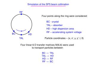
Simulation of Dumped Beam Trajectory ftp beam at 400 GeV, when dumped with 47.3 kV on MKDVs QDA1191 QFA1181 QDA1171 3 x MKDH MKDV1, MKDV2 MKP TIDH MDSH TIDV TBSJB ATC/ABOC days, 23 January 2007
ftp beam at 400 GeV, as we dumped it with 47.3 kV on MKDVs …with +/- 15 % field modulation Centre of beam, deflected by 0.85 x nominal deflection is 47 mm below the SPS centre line ATC/ABOC days, 23 January 2007
(1) Lower 10 % (2) max Upper 10 % Present Beam Dump Position Checked with SEM grid images • Measurement 22/9/06 • varied ‘fine timing’ of MKDV, to sample the MKDV curve (1) • Early Dump (2): expected lower position on block confirmed Extreme positions centre (top = 115 % / bottom = 85 %) between grid line 10 and 16 = 49.4 and 64.35 mm from centre SPS ATC/ABOC days, 23 January 2007
Simulation of Breakdown in Magnet Magnets linked by common PFN Normal ± 15 % oscillation 1 turn of SPS From here on the beam will see less than half the nominal kick G.Vossenberg ATC/ABOC days, 23 January 2007
A brief MKDV history of time… • The original design (SPS 300 / 400 GeV) had two independent MKDV kicker systems • Full redundancy of one magnet: the beam could be properly dumped with only one MKDV magnet • Very good protection against magnet failures • During SPS energy upgrade to 450 GeV the two kicker systems were linked by a common, third PFN. This is the present situation. • If one magnet now breaks down, the short circuit also pulls down the other magnet via the common PFN, one is not any more protected against magnet failure • Still protected against one system not pulsing = missing from switch • Never observed so far (E.Carlier), redundancy of switches • Running without problems for many years • In 2004 some problems with MKDV1 (after scrubbing?) • After end of run in 2004, one week of testing at higher than nominal voltage did not show any problems • However, in 2006 we needed to replace a HV feedthrough and already reduced the operating voltage from original 52 kV to 47 kV to 40 kV due to frequent breakdowns in the MKDV1 magnet • No breakdowns / problems MKDV while running at 40 kV • But limited reliability ATC/ABOC days, 23 January 2007
MKDV future • Shutdown 2006 – 2007 • Repair MKDV magnet, ongoing • Operation at nominal voltage starting 2007 (52 kV) • Further future • Have to regain the full contingency of the MKDV systems by fully separating the MKDV1 and MKV2 systems • Otherwise risk to damage the machine when breakdown in one MKDV magnet while high intensity beam is being dumped • Several options: • Reverse diodes • Two PFNs (modified 2 Ω) with one high current switch each • Two PFNs (modified 2 Ω) with two switches each ATC/ABOC days, 23 January 2007
Conclusions • TIDVG outgassing • Situation of the dump does not seem to be much different from when the first TIDVG was installed about 10 years ago • Careful conditioning with beam not done in 2006 due to lack of time • Partial solution by stopping injection in case of extraction problems • Is not a solution for high intensity MDs • Continue conditioning by beam • Possible local bake out ??? • Gains of local bake out??? • Does not seem to make sense to go for big system modifications / displacement • Could possibly modify the spare TIDVG • Any possible negative effect of graphite dust on adjacent injection kicker magnets not clear • MKDV sparking / reliability • MKDV1 magnet being fixed this shutdown for next start-up • Hope to be able to run at nominal voltages like < 2006 • Should fully separate MKDV1 / MKDV2 systems in the future to obtain full contingency -> reliability ATC/ABOC days, 23 January 2007