Download
1 / 27
350 likes | 1.19k Vues
Advanced Thermodynamics Note 7 Production of Power from Heat. Lecturer: 郭修伯. The power. The efficiency of conventional fossil-fuel steam-power plants rarely exceeds 35%. However, efficiencies greater than 50% can be realized in combined-cycle plants with dual power generation:

E N D
Advanced ThermodynamicsNote 7Production of Power from Heat Lecturer: 郭修伯
The power • The efficiency of conventional fossil-fuel steam-power plants rarely exceeds 35%. However, efficiencies greater than 50% can be realized in combined-cycle plants with dual power generation: • from advanced-technology turbines. • from steam-power cycles operating on heat recovered from hot turbine exhaust gases. • In a conventional power plant the molecular energy of fuel is released by a combustion process. Part of the heat of combustion is converted into mechanical energy.
The steam power plant • The Carnot-engine: • operates reversibly and consists of two isothermal steps connected by two adiabatic steps. • The work produced: • the thermal efficiency: • The thermal efficiency of the Carnot cycle, as a reversible cycle, could be serve as a standard of comparison for actual steam power plants.
Fig 8.1 Fig 8.2
The Rankine cycle • An alternative model cycle taken as the standard, at least for fossil-fuel-burning power plant. Fig 8.3
Fig 8.3 1 → 2: A constant pressure heating process in a boiler. 2 → 3: Reversible, adiabatic (isentropic) expansion of vapor in a turbine to the pressure of the condenser. 3 → 4: A constant-pressure, constant-temperature process in a condenser to produce saturated liquid at point 4. 4 → 1: Reversible, adiabatic (isentropic) pumping of saturated liquid to the pressure of the boiler, producing compressed (subcooled) liquid.
Steam generated in a power plant at a pressure of 8600 kPa and a temperature of 500°C is fed to a turbine. Exhaust from the turbine enters a condenser at 10 kPa, where it is condensed to saturated liquid, which is then pumped to the boiler. (1) What is the thermal efficiency of a Rankine cycle operating at these conditions? (2) What is the thermal efficiency of a practical cycle operating at these conditions if the turbine efficiency and pump efficiency are both 0.75? (3) If the rating of the power cycle of part (2) is 80000kW, what is the steam rate and what are the heat-transfer rates in the boiler and condenser? (1) The enthalpy of superheated steam at 8600 kPa and 500 °C: The turbine (2 → 3) : The enthalpy of saturated liquid at 10 kPa: The condenser (3 → 4): The pump (4 → 1): The boiler (1 → 2):
(2) With a turbine efficiency of 0.75: The enthalpy of saturated liquid at 10 kPa: The condenser (3 → 4): The pump (4 → 1): The net work of the cycle is: The boiler (1 → 2): (3) power rating of 80000kW
The regenerative cycle • |Qboiler| to decrease: high boiler pressures and temperatures • in practice, seldom operate at pressure much above 10,000 kPa or temperature much above 600°C. • |Qcondenser| to decrease: low condenser pressures and temperatures • in fact, the condensation temperature must be higher than the temperature of cooling medium and the condensation pressure as low as practical. • Water from the condenser, rather than being pumped directly back to the boiler, is first heated by steam extracted from the turbine.
Determine the thermal efficiency of the power plant shown in Fig. 8.5, assuming turbine and pump efficiencies of 0.75. If its power rating is 80000 kW, what is the steam rate from the boiler and what are the heat-transfer rates in the boiler and condenser? Basis of 1 kg of steam entering the turbine from the boiler. Because steam is extracted at the end of each section, the flow rate in the turbine decreases from one section to the next one. The amount of steam extracted from the first four sections are determined by energy balances: For saturated liquid water at 226 °C, the steam tables: The fourth increment: Similarly,
Section 1 Fig 8.6 Before entering the turbine: superheated steam at 8600 kPa, t = 500°C Assuming isentropic expansion of steam in section 1 of the turbine to 2900 kPa: The enthalpy of steam leaving section 1: Energy balance on the feedwater heater: based on 1 kg of steam entering the turbine
Section 2 Fig 8.7 Before entering the section 2, m = 0.90626 kg, H = 3151.2 kJ/kg Assuming isentropic expansion of steam in section 2 of the turbine to 1150 kPa. The enthalpy of steam leaving section 2: Energy balance on the feedwater heater:
Section H at section exit Ws for section T at section exit State m of steam extracted 1 3151.2 -240.40 363.65 Superheated vapour 0.09374 2 2987.8 -148.08 272.48 Superheated vapour 0.07928 3 2827.4 -132.65 183.84 Superheated vapour 0.06993 4 2651.3 -133.32 96.00 Wet vapour, x = 0.9919 0.06257 5 2435.9 -149.59 45.83 Wet vapour, x = 0.9378 The net work of the cycle on the basis of 1 kg of steam generated in the boiler:
The efficiency is greatly improved power rating of 80000kW The heat transfer rates in the boiler and condenser are appreciably less.
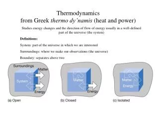
Internal-combustion engines • Steam power plant: • steam is an inert medium to which heat is transferred from a burning fuel or from a nuclear reactor • Steam absorbs heat at a high temperature in the boiler. • Steam rejects heat at a relatively low temperature in the condenser. • Internal combustion engine: • No working medium • a fuel is burned within the engine and the combustion products serve as the working medium. • High temperatures are internal and do not involve heat-transfer surfaces. • Air as the working fluid
The Otto Engine The most common internal-combustion engine, because of it used in automobiles. 1st stroke: 0 → 1: At essentially constant pressure, a piston moving outward draws a fuel/air mixture into a cylinder. 2nd stroke: 1 → 2 → 3: all valves are closed, the fuel/air mixture is compressed, approximately adiabatically along 1 → 2; the mixture is then ignited, and combustion occurs so rapidly that the volume remains nearly constant while the pressure rises along 2 → 3. 3rd stroke: 3 → 4 → 1: the work is produced. Approximately adiabatically expand 3 → 4; the exhaust valves opens and the pressure falls rapidly at nearly constant volume along 4 → 1. 4th stroke: 1 → 0: the piston pushes the remaining combustion gases from the cylinder. The compression ratio: The efficiency of engine (i.e., the work produced per unit quantity of fuel) The air-standard Otto cycle: two adiabatic and two constant-volume steps, which comprise a heat-engine cycle for which air is the working fluid.
The Otto Engine Fig 8.8 Fig 8.9
Fig 8.9, the thermal efficiency Ideal gas
The diesel engine • Differs from the Otto engine: the temperature at the end of compression is sufficiently high that combustion is initiated spontaneously. • Higher compression ratio → the compression step to a higher pressure → higher temperature results. • The fuel is injected at the end of the compression step • The fuel is added slowly enough → the combustion process occurs at approximately constant pressure. • At the same compression ratio: • However, the diesel engine operates at higher compression ratios and consequently at higher efficiencies.
Fig 8.10 On the basis of 1 mol of air (ideal gas), the heat quantities absorbed in step DA: the heat rejected in step BC: Reversible, adiabatic expansion (step AB): Reversible, adiabatic compression (step CD): The compression ratio: The expansion ratio: the thermal efficiency:
The gas-turbine engine • The Otto and diesel engines use the high energy of high-temperature, high-pressure gases acting on the piston within a cylinder. However, turbines are more efficient than reciprocating engines. • The advantages of internal combustion are combined with those of the turbine. • The air is compressed to several bars and enters the combustion chamber. • The higher the temperature of the combustion gases entering the turbine, the higher the efficiency of the unit. • The centrifugal compressor operates on the same shaft as the turbine, and part of the work of the turbine serves to drive the compressor.
Fig 8.11 Fig 8.12 The Brayton cycle: AB → reversible adiabatic compression. BC →heat QBC is added. CD → isentropic expansion. DA → constant-pressure cooling.
Based on 1 mol of air, the thermal efficiency: The work done as the air passes through the compressor: The heat addition: Isentropic expansion in the turbine: Isentropic expansion:
A gas-turbine engine with a compression ratio PB/PA = 6 operates with air entering the compressor at 25°C. If the maximum permissible temperature in the turbine is 760°C, determine: (1) the efficiency η of the ideal cycle for these conditions if γ = 1.4. (2) the thermal efficiency of an air cycle for the given conditions if the compressor and turbine operate adiabatically but irreversibly with efficiencies ηc = 0.83 and ηt = 0.86. (1) (2) The temperature after irreversible compression in the compressor TB is higher than the temperature after isentropic compression T’B and the temperature after irreversible expansion in the turbine TD is higher than the temperature after isentropic expansion T’D.
Jet engines; rocket engines • The power is available as kinetic energy in the jet of exhaust gases leaving the nozzle. • Jet engines: a compression device + a combustion chamber + a nozzle • Rocket engines: differ from a jet engine in that the oxidizing agent is carried with the engine.
Fig 8.13 Fig 8.14