Analysis of FORTIS Rocket-Borne Far-UV Spectro-telescope Preparations and Initial Testing
The FORTIS (Far-Ultraviolet Off Rowland-circle Telescope for Imaging and Spectroscopy) is a rocket-borne multi-object spectro-telescope designed to explore Lyman alpha (Lya) escape from star-forming galaxies and its correlation to the gas-to-dust ratio. This paper reports on the preparation and end-to-end testing of FORTIS, including innovations like the microshutter array derived from JWST/NIRSPEC. We emphasize the performance of instruments and their effective area, highlighting the meaningful data from initial observations and testing that pave the way for future missions.

Analysis of FORTIS Rocket-Borne Far-UV Spectro-telescope Preparations and Initial Testing
E N D
Presentation Transcript
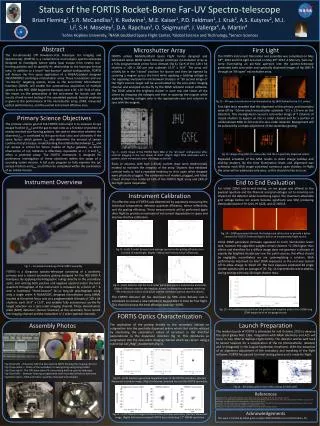
Status of the FORTIS Rocket-Borne Far-UV Spectro-telescope Brian Fleming1, S.R. McCandliss1, K. Redwine1, M.E. Kaiser1, P.D. Feldman1, J. Kruk2, A.S. Kutyrev2, M.J. Li2, S.H. Moseley2, D.A. Rapchun3, O. Seigmund4, J. Vallerga4, A. Martin4 1Johns Hopkins University, 2NASA Goddard Space Flight Center, 3Global Science and Technology, 4Sensor Sciences Abstract The Far-ultraviolet Off Rowland-circle Telescope for Imaging and Spectroscopy (FORTIS) is a rocket-borne multi-object spectro-telescope designed to investigate Lyman alpha (Lya) escape from nearby star-forming galaxies and to quantify its relationship to the local gas-to-dust ratio. In addition to a novel "two-bounce" optical configuration, FORTIS will feature the first space application of a NASA/Goddard designed JWST/NIRSPEC prototype microshutter array.These innovations and our "on-the-fly" targeting system, know as the Zero-Order Microshutter Interface (ZOMI), will enable the autonomous acquisition of multiple spectra in the 900 -1800 Angstrom bandpass over a 30' x 30' field of view. We report on the preparation of the instrument for launch and the results of end-to-end testing of the assembled payload. Special emphasis is given to the performance of the microshutterarray, ZOMI, measured optical performances, and the overall instrument effective area. Microshutter Array FORTIS utilizes NASA/Goddard Space Flight Center designed and fabricated James Webb Space Telescope prototype microshutter array as a fully programmable prime focus slitmask (fig 6). Each of the 128 x 64 shutters is 100 x 200 μm and subtends 15.9” x 36.9”. The array will initially be in the “closed” position for launch and then be opened by scanning a magnet across the front while applying a latching voltage to the opposing row/column rails between shutters. A ~30 second image of the flight science target will be accumulated by the zero-order imaging channel and analyzed on-the-fly by the ZOMI onboard control software. The ZOMI selects the brightest shutter in each row and closes all the others by dropping the voltages and then re-scanning the magnet while applying latching voltages only to the appropriate rows and columns in sync with the magnet. Fig. 7 – (Left) Image of the FORTIS flight MSA in the “all open” configuration after contrast plugging in the test dewar at GSFC. (Right) Flight MSA addressed with a pattern, taken immediately after the image on the left. Rows or columns with high (>30uA) current draw were electronically masked to maintain the integrity of the array. Shutters that exhibited contrast leaks or had a repeated tendency to stick open when dropped were physically plugged. The combination of masked, plugged, and failed closed shutters has rendered 15% of the FORTIS flight array and 24% of the flight spare inoperable. First Light The FORTIS instrument fabrication and assembly was completed on May 28th, 2012 and first light occurred on May 29th 2012. A Mercury “pen-ray” lamp illuminating an pin-hole aperture into the spectro-telescope generated both zero-order and spectrally dispersed images of Hg 1845 Å through an “All-open” microshutter array. Fig 12 – All open microshutter array illuminated by Hg 1845 flanked by the +/-1 orders. First light tests revealed that the alignment of the primary and secondary were off by ~10mm (each microshutter subtends ~0.5 x 1.0 mm on the detector). This misalignment caused a zero-order image of 7 columns of closed shutters to appear on the +1 order channel and for a portion of unilluminated MSA to fall onto the zero-order detector. Realignment will be achieved by a simple adjustment of the secondary grating. Fig 13 –image of Hg 1845 Å in zero-order and the ±1 spectrally dispersed orders. Repeated actuation of the MSA results in static charge buildup and sticking shutters. By the time illumination levels and alignment was achieved, each MSA image contained numerous open shutters. In-flight the array will be addressed only once, so this should not be an issue. Primary Science Objectives The primary science goal of the FORTIS instrument is to measure to Lyα escape fraction (fLyα) and the gas-to-dust ratio as a function of position in nearby resolved star-forming galaxies. We seek to determine whether the observed fLyα is correlated to the gas-to-dust ratio and ultimately if the same factors which govern fLyα also determine the amount of Lyman continuum (LyC) escape. Understanding the relationship between fLyαand LyC escape is critical for future studies of high-z galaxies, as direct observation of LyC radiation is effectively impossible at z > 3 and fLyαoffers a potential proxy. The FORTIS instrumentis designed for preliminary investigation of these objectives within the scope of a sounding rocket mission. A full scale program to fully examine the LyC escape fraction and fLyα could then be completed within the parameters of an orbital mission. Instrument Overview Fig. 1 – Annotated rendering of the FORTIS assembly FORTIS is a Gregorian spectro-telescope consisting of a parabolic primary and a triaxial secondary grating designed for the 900-1800 Å bandpass. By applying the holographic rulings directly to the secondary optic, and utilizing both positive and negative spectral orders the total quantum throughput of the instrument is increased by a factor of ~ 6 over a traditional "three-bounce” far-uv long-slit spectrograph using only a single order. A NASA/GSFC designed microshutter array (MSA) located at the prime focus acts as a programmable slitmask of 128 x 64 shutters, each 36.9” x 15.9”, and enables fully autonomous on-the-fly target selection via a zero-order imaging channel. Three microchannel plate (MCP) detectors (Sensor Sciences) at the secondary focus record the imaging channel and the redundant +/-1 order spectral channels. End to End Evaluation For initial ZOMI end-to-end testing, an ion gauge was affixed to the payload aperture and the filament and grid voltages set to minimize ion impact on the detector while maximizing signal. The maximum attainable grid voltage before ion events became significant was 50V, producing detectable levels of HI 1216, HI 1026, and OI 1304 Å. Fig. 14 – ZOMI generated slitmask. No background subtraction to provide a better contrast for 1026 Å. Scattered light is due to an uncolumnated light source. Initial ZOMI generated slitmasks appeared to track illumination levels well, however the algorithm weights certain shutters ~5-10% higher than others and therefore for a diffuse image does not generate a slitmask of exactly the brightest shutter per row. For point sources, this effect should be negligible, nevertheless we are contemplating a solution. MSA performance improved on later ZOMI exposures as the unit was turned off to allow charge to bleed off. The best exposure produced 28 single shutter spectra with an average of 26. Fig. 14 repreents the worst address during testing with only 20 single shutter rows. Fig. 15 – 44 combined spectra from the positive and negative orders for a 1000s long ZOMI exposure of an ion gauge source. Instrument Calibration The effective area of FORTIS was determined by separately measuring the individual components; detector quantum efficiency, mirror reflectivity, and the grating efficiency. These measurements will be performed again after flight to provide an estimate of instrument degradation in space and improve the flux calibration. Fig. 8 – (Left) 0-order (crosses) and average spectral order grating efficiency as a function of wavelength. (Right) – Measured Primary mirror reflectivity. Fig. 9 – (Left) Detector QEs for the 0-order (gold) and spectral orders (blue and black). (Right) –Effective areas for the imaging channel, including the achromat, which has ~0% transmission below 1216 (blue) and the combined spectral channels (black). The FORTIS detector QE has decreased by 50% since delivery and is scheduled to receive a new cathode in August 2012 in time for first flight. This should increase the total effective areas by ~100%. FORTIS Optics Characterization The application of the grating directly to the secondary induces an astigmatism into the spectrally dispersed orders which that can be reduced by shortening the secondary's radius of curvature in the direction perpendicular to the dispersion direction (fig 3). This introduces an astigmatism into the zero-order imaging channel which we correct using a cylindrical CaF2/MgF2 doublet lens (fig 5). Fig.10 – (Left) Raytrace generated tangential focus of the FORTIS secondary. (Center) Measured secondary image. (Right) Achromat corrected focus of the FORTIS secondary. Fig.11 – (Left) Raytracetangential focus of the primary+secondary. (Center)Measured image. (Right)Achromatcorrected FORTIS focus indicating 2.7” FWHM resolution Launch Preparation The maiden launch of FORTIS is scheduled for mid-October, 2012 to observe the spiral galaxy NGC 1365. Integration with NASA telemetry and ACS will occur in July, 2012 at Wallops Flight Facility. The detector will be sent back to Sensor Sciences for a reapplication of the CsI photocathode, retested, and re-integrated in the August-September timeframe. With the exception of an alignment adjustment of the secondary and tweaking of the flight software, FORTIS has passed its initial testing phase and is ready for flight. Fig 16 – Simulated spectra with MSA overlay for NGC1365. Assembly Photos Fig 2 (top left) – Detectors with the two spectral MCPs flanking the imaging channel. Fig 3 (top center) – Photo of the secondary tri-axial grating and grating holder. Fig 4 (top right) – The JHU team (sans PI) surrounding built up spectro-telescope. Fig 5 (bot left) – Detector housing and gatevalve with mounted cylindrical achromat. Fig 6 (bot right) – MSA and motor assembly mounted and installed. • References • McCandlissS.R. et al. 2004. FORTIS: Pathfinder to the Lyman Continuum. Proceedings of the SPIE, Vol. 5488, pp. 709-718 • Kutyrev, A. S. et al. 2004. Programmable Microshutter Arrays for the JWST NIRSpec: Optical Performance. IEEE J. Select. Topics Quantum Electron. 10, pp. 652-718 • McCandliss, S.R. 2008. Project Lyman. SPIE Conference, Volume 7011, pp. 20:1-12 • McCandliss, S.R. 2009. Project Lyman: Resolving the Physics Behind Reionization. Astro2010: The Astronomy and Astrophysics Decadal Survey, vol. 2010, pp. 196 • McCandliss, S.R. et al. 2010. Fabrication of FORTIS. Proceedings of SPIE, Vol. 7732 • Fleming, B. et al. 2011. Fabrication and Calibration of FORTIS. Proceedings of SPIE, Vol. 8145, pp. 245 Acknowledgements This work is funded by NASA grant numberNNX11AG54Gto JHU (McCandliss, PI).