Download
1 / 62
760 likes | 1.96k Vues
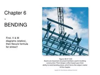
Mechanacs of Materials. Ch.6 Bending stress. Chapter 6 Bending stress. 6.1 Introduction 6.2 Normal stresses in beams 6.3 Shear stresses in beams 6.4 Strength criteria of beams 6.5 Optimum design of beams for stength

E N D
Mechanacs of Materials Ch.6 Bending stress LIU Jiemin @SJZU 2008
Chapter 6 Bending stress 6.1 Introduction 6.2 Normal stresses in beams 6.3 Shear stresses in beams 6.4 Strength criteria of beams 6.5 Optimum design of beams for stength 6.6 Combined bending and axial load; core of sections LIU Jiemin @SJZU 2008
Chapter 6 Bending stress 6.1 Introduction 6.2 Normal stresses in beams 6.3 Shear stresses in beams 6.4 Strength criteria of beams 6.5 Optimum design of beams for stength 6.6 Combined bending and axial load; core of sections LIU Jiemin @SJZU 2008
Bending shear stresst Bending nornal stress s 6.1 Introduction Internal forces and stresses in beams Fs Internal Forces M q Me B A
Chapter 6 Bending stress 6.1 Introduction 6.2 Normal stresses in beams 6.3 Shear stresses in beams 6.4 Strength criteria of beams 6.5 Optimum design of beams for stength 6.6 Combined bending and axial load; core of sections LIU Jiemin @SJZU 2008
F F a a A B x F x F M Fa 6.2 Normal stresses in beams 6.2.1 Test and plane assumption Pure Bending: ☆平面假设
Longitudinal symmetry surface Neutral layer Cross-section Neutrai axis 6.2 Normal stresses in beams What’s the location of neutral(layer) axia?
中性轴 c d a b 纵向对称面 中性层 M M c d a b 6.2 Normal stresses in beams 横向线(a b、c d)变形后仍为直线,但有转动;纵向线变为曲线,且上缩下伸;横向线与纵向线变形后仍正交。
x y a a y dq r dx y 6.2 Normal stresses in beams 6.3.2 Bending normal stress z(中性轴) 1. Geometry equation 2. Hooe’s law dx
(a) EIz Bending stiffness 6.2 Normal stresses in beams 3. Equilibrium (b) Conclusion: Neutral axis passes the concentroid!
d a = d b D D h H B 6.2 Normal stresses in beams 6.3.3 Maximum normal stress Wz:Torsional section modulus
l Me 6.2 Normal stresses in beams Ex.6.1 Determineσmax and curvature radius ρof the cantilever beam and shown. Knowing: I of №.18. Me=20kNm Solution: 1. Analysis of internal forces and stress 2. Deformation analysis
6.2 Normal stresses in beams 6.5.4 Normal stress in the case of lateral bending There are normal stress and shear stress on the cross-section of a beam under lateral loads. Validity approximately
30 180 1 2 z 120 y + x + ql2/8 M(x) 6.2 Normal stresses in beams Ex.2 Shown is the beam subjected to uniform loads q. Determine: (1)σat point 1 and 2 on section 1-1; (2)σmax on the section 1-1 (3)σmax in the bean; (4)ρof section 1-1, knowing: E=200GPa. 1-1 q=60kN/m B A 1m 2m Solution:(1)Plot M diagram M1
30 180 1 2 z 120 y 6.2 Normal stresses in beams (1)Normal stress at points 1, 2
1 2 120 6.2 Normal stresses in beams (2) σ1,maxon the section 1-1 (3) σmaxin the bean Critical section:Middle section Critical point: Upper and lower edges (3)ρof section 1-1
6.2 Normal stresses in beams 2.两个概念 中性层:梁内一层纤维既不伸长也不缩短,因而纤维不受拉应力和压应力,此层纤维称中性层。 中性轴:中性层与横截面的交线。 3.假设 平面假设:横截面变形后仍为平面,只是绕中性轴发生转动,距中性轴等高处,变形相等。 横向纤维互不挤压假设 (可由对称性及无限分割法证明)
Chapter 6 Bending stress 6.1 Introduction 6.2 Normal stresses in beams 6.3 Shear stresses in beams 6.4 Strength criteria of beams 6.5 Optimum design of beams for stength 6.6 Combined bending and axial load; core of sections LIU Jiemin @SJZU 2008
Fs 6.3 Shearing stress in bending q Me B A M+dM M Fs dx
dx z y y* Fs t1 x t y b 6.3 Shearing stress in bending 6.3.1 Shear stress on rectangular section • Assumptions: Shear stress is parallel to shear force;Shear stress is uniform along width. M M+dM Fs 2. From Fig. a
M M+dM y y* Fs Fs dx z t1 x b t s s1 y 6.3 Shearing stress in bending FromTheory of conjugate shear stress
Fs 6.3 Shearing stress in bending Fs: Shear force on the section;Sz (ω) : Static moment of the area of the side of line y to the neutral axis; Iz: inertia moment of the whole area to the neutral axis. Direction ofτ:Direction of the Fs Distribution of τ:Uniform along width, and parabola along height. Maximum shear stress is equal to 1.5 times of average shear stress.
①Standard I-steel shapes: Af —Area of thew web. Fs f Fs t ; » max A 6.3 Shearing stress in bending 6.3.2 Maximum shear stresses of common sections Conclusions:95~97% of vertical shear stress is carried by web, and tmax≈ tmin; In the flanges there are a little of vertical and horizontal shear stresses.
Z(中性轴) h H b Web Flange 6.3 Shearing stress in bending ② Non-standard I-steel shapes 腹板上的剪应力: 最大剪应力:
6.3 Shearing stress in bending ② circular cross-section: Fs Assume that τy to be uniform along hypotenuse AB z τmax takes place at the neutral axis A B
Fs P z h Fs x e e e y 6.3 Shearing stress in bending ③Thin-walled circular cylinder: ④Channels:
Chapter 6 Bending stress 6.1 Introduction 6.2 Normal stresses in beams 6.3 Shear stresses in beams 6.4 Strength criteria of beams 6.5 Optimum design of beams for stength 6.6 Combined bending and axial load; core of sections LIU Jiemin @SJZU 2008
5.5 Strength conditions of normal stress and shearing stress in beams 1. Strength conditions of normal stress and shearing stress 2. Types of strength calculations: Strength check: Design section: Find allowable load:
t s t s s 3.Analysis of critical section and critical point ① For uniform section beams, σmax takes place at the upper and lower edges, ②τmaxtakes place at the neutral axis of the cross-section on which there is Fs,max. Fs, max Mmax
4.Special cases necessary for shear stress chesk Span of a beam is small,M smaller,and Fs larger。 For materials (wood)whose capability of resisting shear is bad. Non-standard combined section members, ratio of the web to flange is smaller.
Fs – + x + x Ex.1 Shown is a Rectangular section beam (bh=0.12m0.18m). []=7MPa,[]=0. 9 MPa,Determine ratio of σmax toτmax, and check strength of the beam. q=3.6kN/m B A L=3m Solution:Plot M diagram
Fs – + x + x Find maximum stresses q=3.6kN/m A Strength is OK. Ratio of stresses
FBy FAy 4kNm M x M 2.5kNm A1 y1 C y2 A2 Ex.6.2 Cast iron beam of T-section. [t]=30MPa,[c]=60 MPa,C is centriod,y1=52mm, y2=88mm,Iz=763cm4,Check the strength of the beam. How does the beam lie rationally? P1=9kN P2=4kN A C B D 1m 1m 1m Solution: Plot M-diagram A3 Critical points A4
2.5kNm M 4kNm A1 y1 A3 C y2 y2 ”T” is rational, “ ”is not rational C y1 A2 A4 Check the strength
Ex.6.3 The cantilever beam of rectangular section is subjected to Fy and Fz . Knowing Fy = Fz = F = 1.0 kN, h = 80 mm,b = 40 mm ,a = 800 mm, [σ]=160 MPa. Check the strength of the beam。 Solution:①Internal forces ②Stress and Strength
k MzA d z MyA y ③Discussion Two-dimensional bending, neutral axis passes through the centriod of the section 危险点:d
Chapter 6 Bending stress 6.1 Introduction 6.2 Normal stresses in beams 6.3 Shear stresses in beams 6.4 Strength criteria of beams 6.5 Optimum design of beams for stength 6.6 Combined bending and axial load; core of sections LIU Jiemin @SJZU 2008
6.5 Optimum design of the beams for strength Mmax wZ Two ways of enhancing strenth of beams
6.5 Optimum design of the beams for strength Optimum strength h R Optimum stiffness b 6.5.1 Optimum sections of the beam 1. Rectangular section From theory of M.M: Proof:Make maximum stress to get extreme value。
6.5 Optimum design of the beams for strength z D z a a 2. Discussion of optimum sections ①在面积相等的情况下,选择抗弯模量大的截面
6.5 Optimum design of the beams for strength z z 2a 2a 1.6a 0.8a a a 工字形截面与框形截面类似。
6.5 Optimum design of the beams for strength z yt C s C Z yc • 对于铸铁类抗拉、压能力不同的材料,最好使用T字形类的截面,并使中性轴偏于抗变形能力弱的一方,即:若抗拉能力弱,而梁的危险截面处又上侧受拉,则应如下左图示放置。 3、根据材料特性选择截面形状
6.5 Optimum design of the beams for strength P x (二)采用变截面梁 最好是等强度梁,即 若为等强度矩形截面,则高为 同时
6.5 Optimum design of the beams for strength l ql2/50 ql2/50 + ql2/40 + x x + ql2/8 M(x) M(x) 6.5.3 Optimum arrangement of external forces acting in the beams 1. Reduce the span of the beam q q B A 0.6l 0.2l 0.2l
6.5 Optimum design of the beams for strength x x Fl/8 M F M Fl/4 2. Chang one concentrated force to several ones F/2 F/2 F l/4 l/4 2l/4 A B B A l/2 l/2 3. Increase restraints
Chapter 6 Bending stress 6.1 Introduction 6.2 Normal stresses in beams 6.3 Shear stresses in beams 6.4 Strength criteria of beams 6.5 Optimum design of beams for stength 6.6 Combined bending and axial load; core of sections LIU Jiemin @SJZU 2008
k F m m d F z FN M y 6.6 Combined bending and axial load; Core of section 1. Combined bending and axial load = ③讨论
F F Mz My MZ F B x A y z My 6.6 Combined bending and axial load; Core of section 2. Eccentric Compression x y Mz z At point A At point B
FC FAx B FAy F 6.6 Combined bending and axial load; Core of section D Example 6.6 800 C Knowing: F=8 kN, [σ]=10MPa, select the type of the I-shaped beam AB α B 2500 1500 F A Solution: (1) Find reactions
FAx C FC B - - ○ ○ FAy F 6.6 Combined bending and axial load; Core of section (2) Draw internal-force-diagraphs (3) Determine critical section Section C- 12kNm (4) Design section size M x At first, determine the size by Mmax only FN x 40kN