Download

1 / 21
210 likes | 343 Vues
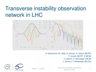
This study investigates the causes of transverse instability observed in the Main Injector (MI) beam profiles using various instrumentation and analysis techniques. Initially inspired by noisy profiles, adjustments were made to high voltage settings and instrumentation to capture high-resolution data. The findings highlight the absence of vertical oscillations at injection energies and minor oscillations at higher energies, with notable differences in stability among various beam bunches. Effective chromaticity adjustments proved beneficial in mitigating oscillation issues, enhancing beam quality and stability during transfers.

E N D
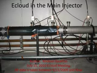
Pbar Transverse Instabilityin Main Injector Ming-Jen Yang, Main Injector Jim Zagel, Instrumentation 04/12/2010
Study • Initially motivated by • Noisy in MI flying wire beam profile • Changed PMT high voltage • Replaced PMT paddle in the tunnel • Noisy only on pbar from RR. • Installed RTD720 digitizer at MI10 • Digitize monitor signal supplied by FW system • Raw PMT signal • FW integrated loss signal. • Independent of FW front end • Turn-by-turn. • No decimation.
First data set, S7669x1 Output of MI FW integrator, integrating over four pbar bunches. Break-down occurred when signal was too large.
Acc. to RR transfer, for comparison Scale of oscillation is quite a bit smaller. MI transverse plane damper are in use for this type of transfers.
S7685x1 Pbarfrom RR, Vertical Flying Wire There is no apparent vertical plane oscillation at 8-GeV.
150 GeV pbar, S7706x1 Horizontal Flying Wire No apparent horizontal plane oscillation at 150 GeV.
S7682x1, with PMT paddle replaced No break-down, but Oscillation is still as big as before.
Reconstructed horizontal beam profile bunch# 1 bunch# 2 bunch# 4 bunch# 3 Peak integrated amplitude from each successive traces, for each bunch.
Horizontal beam profile, as reported by FW bunch# 1 bunch# 2 bunch# 4 bunch# 3 Good agreement with the reconstructed profiles shown in previous slide.
FFT on reconstructed profile, bunch #3 FFT spectrum from TBT BPM position at injection. 39136.4 Hz Tune = 39136.4 / 89815.3 = 0.4357 FFT spectrum of bunch#3 profile.
Observation • Hashing in the profile • Result of betatron oscillation • Give the same Tune as measured with TBT BPM. • Bunch # 1 • Minimal oscillation. • Clean profile from both version. • Bunch #3 • Substantial oscillation. • Noisy FW profile. • Bunch #2 & #4 • Comparison not as clear-cut. • Double peak feature • Caused by PMT break-down. • Disappeared with reduced high voltage. • FW profiles are similar to the reconstructed profiles.
Adjusting MI chromaticity, nominal setting S7724, xfer #1 Chrom. H: -12 Chrom. V: -13 Oscillation: large FWH integrator signal Color legend: Outside plate Inside plate Difference MI horizontal wide-band pickup
Adjusting MI chromaticity, -3 units S7724, xfer #1 Chrom. H: -15 Chrom. V: -16 Oscillation: smaller FWH integrator signal Legend: Signal - Outside plate Signal - inside plate Signal Difference MI horizontal wide-band pickup
Adjusting MI chromaticity, -6 units S7724, xfer #1 Chrom. H: -18 Chrom. V: -19 Oscillation: invisible FWH integrator signal Legend: Signal - Outside plate Signal - inside plate Signal Difference MI horizontal wide-band pickup
Adjusting MI chromaticity, -12 units S7724, xfer #1 Chrom. H: -24 Chrom. V: -25 Oscillation: invisible FWH integrator signal Legend: Signal - Outside plate Signal - inside plate Signal Difference MI horizontal wide-band pickup
Signal of Wide-band, at injection Nearly perfect beam with no sign of beam distortion from RR.
Wall Current Monitor signal, pbar bunch #1 Long profile: at injection Long profile: when flying wire flew
Wall Current Monitor signal, pbar bunch #2 Long profile: at injection Long profile: when flying wire flew
Wall Current Monitor signal, pbar bunch #3 Long profile: at injection Long profile: when flying wire flew
Wall Current Monitor signal, pbar bunch #4 Long profile: at injection Long profile: when flying wire flew
Summary • At injection • No visible beam profile distortion. • Neither longitudinal nor horizontal. • At the time when flying wire flew • Horizontal plane • Bunch #1 show the least amount of distortion. • Bunch #3 & #4 are the worst. • Profiles deteriorated, horizontal and longitudinal. • Vertical plane • None. • At 150 GeV • None. • Pbar from Accumulator to RR • Visible, but smaller, horizontal plane oscillation. • MI transverse damper is in used for these transfers. • Chromaticity damping • Effective. • Set chromaticity to -18 units, from nominal of -12.