Download
1 / 47
500 likes | 718 Vues
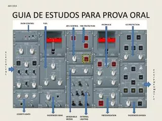
AKD 2010. GUIA DE ESTUDOS PARA PROVA ORAL. DVDR CONTROL. FUEL. HYDRAULIC. ICE PROTECTION. APU CONTROL. FIRE PROTECTION. ELECTR I CAL. ECS/PNEUMATIC. COCKPIT LIGHTS. PASSENGER SIGNS. PRESSURIZATION. PASSENGER OXYGEN. WINDSHIELD WIPERS. EXTERNAL LIGHTING. DVDR CONTROL.

E N D
AKD 2010 GUIA DE ESTUDOS PARA PROVA ORAL DVDR CONTROL FUEL HYDRAULIC ICE PROTECTION APU CONTROL FIRE PROTECTION ELECTR I CAL ECS/PNEUMATIC COCKPIT LIGHTS PASSENGER SIGNS PRESSURIZATION PASSENGER OXYGEN WINDSHIELD WIPERS EXTERNAL LIGHTING
DVDR CONTROL SelectorSwicht :Enable to testthe tone ofthe DVDR 1 (FWD) or DVDR 2 (AFT) to beheardwhen a headset in plugged in to thejack. HEADPHONE Jack : Allows a headset to beinsert to monitor thecompositeaudio output ofthe DVDR unitduringtests and normal operations. DVDR TEST: Commands a selftestof DVDR 1 and 2 . EICAS advisorymessage - CVR AFT (FWD) FAIL 1- What are you checking for when you press the test button? Verify no fail displayed on EICAS. DVDR ERASE : Allows CVR data to beerasewhentheaircrafts is ON THE GROUND withthe PARKING BRAKE SET
ELECTRICAL (AC) IDG 1 and 2 Selector Knob: GROUND POWER UNIT (GPU) BUTTON : PUSHED IN – Conectsthe AC GPU to the AC BUS TIE , according to the source priority PUSHED OUT – Isolatesthe AC GPU fromthe AC BUS TIE PUSH IN - Allowsautomaticoperatiooftheelectrical system. Thispositionconnectsthe APU generator to the AC BUS TIE according to the source priority. PUSH OUT - Opens the APU generator conector and isolatesthe APU generatorfromthe AC BUS TIE. The APU generator is tripped off and de-excited. AVAIL light illuminateswhenthe AC GPU is properlyconnected and the AC powerrequirements are satisfied. IN USE light – pushed in / AC GPU is powering AC BUS TIE
ELECTRICAL (DC) TRU ESS Toggle Switch: AUTO – Allowsautomaticoperationoftheelectrical system. Thisposition connectsthe TRU ESS to the ESS BUS 3. OFF – Isolatesthe TRU ESS fromthe ESS BUS 3. 1 - Why is there an AUTO position on BATT 2? BATT 2 supplies the APU START BUS during APU starting. TRU 1 and TRU 2 Toggle Switch: AUTO – Allowsautomaticoperationof theelectrical system. This positionconnectsthe TRU to therespective DC BUS. OFF – Isolatesthe TRU fromthe respective DC BUS. BATT 2 Selector Knob: AUTO – Allowsautomaticoperationofthe electrical system. ConnectsBatt 2 to the DC ESS BUS 2. OFF – Thebatterysuppliespower to the HOT BATT BUS 2 only. BATT 1 Selector Knob: ON- Battconnected to DC ESS BUS 1. OFF- Battsupply HOT BATT BUS. 2- What is the minimum voltage? 22.5 VDC. DC BUS TIE Toggle Switch: AUTO – Allowsautomaticoperationoftheelectrical system. Thisposition controlstheoperationofthe DC Tie Contactors (ETCs/DCTC). According to the system logic. OFF – Opens alltiecontactors. Suppliesthe FADEC.
COCKPIT LIGHTS Panel PEDESTAL Knob: Turns ON/OFF and sets pedestal lightingbrightness. MAIN PNL Knob: Turns ON/OFF and sets thelightingbrightness OftheGuidancePanel (GP) and instrumentPanel Background lighting. DOME Light Switch: Batteriesmustbe ON/AUTO to have DOME lights ON. ANNUNCIATORS TEST Button: OVHD PNL Knob: Turns ON/OFF and sets thebrightnessof The Overhead Panel’s background lighting. Rotatingthe knob to the OFF positionwill Illuminateallannunciatorlights to full bright. Thestripebars and captionindications in allmainpanel, overhead panel and control pedestal pushbuttons Illuminatewhenpressed, allowingverificationoflampintegrity. Olnlythe EMRG/PRKG BRAKE light, GPU pushbutton light, and firetestlights are notilluminated. 1 - What are you checking for when you push the ANNUNCIATOR PANEL TEST Button? The lamp integrity of all striped bars and caption indication of all main panel, overhead panel, and control pedestal.
FUEL Panel XFEED Selector Knob: LOW 1 – Opens thexfeed valve, and activates AC PUMP 2 to supplyfuel to both enginesfromtherightwingtank. OFF – Closes thexfeed valve. LOW 2 – Opens thexfeed valve , and activates AC PUMP 1 to supplyfuel to both enginesfromtheleftwingtank. DC PUMP: OFF – Deactivatesthe DC fuelpump AUTO – Allowsautomaticoperationofthe DC PUMP in accordancewithS.L. ON – Activatesthe DC fuelpump. Ifthe APU is inoperative and no AC groundpower is avbl, the DC FUEL PUMP willbeused for initialfuelsupply. The DC PUMP is not a backup for the AC pump. LIMITATION AC PUMP 1 and AC PUMP 2: OFF – Deactivatestheassociated AC PUMP AUTO – Allowsautomaticoperationoftheassociated AC PUMP in accordancewithS.L. (system logic) ON – Activatestheassociated AC PUMP The AC PUMP willactivateautomaticallywhenfuelpressure Is demanded and ejector output is insufficient (engine start or Ejectorpumpfailure), and for xfeedoperation.
PASSENGER SIGNS Panel ATTND CALL Button: Pressingthisbuttonsounds a chime in passengercabin and illuminatestheGREEN light ontheFltAttndrainbow EMER LT Selector Knob: OFF – Disablesautomaticoperationof theemergencylights. Thelights can still beturnedonfromthe FWD or AFT ATTENDANT panel. ARMED – Automaticallyilluminatesall emergencylightsif DC BUS 1 losespoweroriftheairplane electricalpower is turned off. ON – Turnsonallemergencylights regardlessofthepositionofthe EMERGENCY LIGHT switch onthe FWD and AFT ATTENDANT panels. FSTN SEAT BELTS Toggle Switch: ON – Illuminatesthe FASTEN SEAT BELTS signs. Turning the switch ON sounds a singlelow tone chime in thecabin, lavatories and galleys. OFF – Turns off the FASTEN SEAT BELTS signs. Turning the switch off sounds a singlelowchime in the cabin NO SMKG NO SMKG Toggle Switch: ON – Illuminatesthe NO SMOKING signs. Turningthe switch ON a singlelow tone chime in thecabin. OFF - Turns off the NO SMOKING signs. Turningthe switch OFF sounds a single lowchime in thecabin. NOTE: Thebothsigns (NO SMKG and FSTN BELTS) willautomaticallyilluminatewhentheOxygenMasks are commanded to deploy. STERILE Toggle Switch: ON – IlluminatestheAMBERsterile light ontheFltAttndrainbow. Turningthe switch ON sounds a singlehigh tone chime in thecabin OFF – Turns off theAMBERsterile light ontheFltAttndrainbow. 1 - How long will the batteries supply emergency power? (ELPU’s) Approximately 10 minutes.
FIRE EXTINGUISHER Panel CARGO SMOKE FWD and AFT Buttons (GUARDED): Momentaryactionpushbutton. Illuminateswhenthehigh rate bottle is armed. #1 and #2 Engine Fire EXTG Handle: Illuminateswhenfire is detected. PULL – Closes theassociatedenginebleedair, fuel and hydraulicshutoffvalves. Theunderspeedlogicwilleventually open thegeneratorlinecontactor as theenginedeacelerates. ROTATE (left (A) orright (B)) – Dischargestheassociatedfireextinguisherbottleintotheassociatedengine. Fire Detection System TEST Button – Testtheengines and APU firedetection systems, and the FWD / AFT cargo compartmentsmokedetection system. Checkthere no EICAS MSG’sbefore do thetest: FIRE DET FAIL, FIREX FAIL, FIREX ARM, BTL DISCH. APU (GUARDED): Momentaryactionpushbutton. Closes the APU fuelshutoff valve and dischargesthe APU fireextinguisherbottle. The light willilluminatewhenthe APU EMER STOP buttonhasbeenpushed in whenan APU firehasbeendetected, or 60 secondsafter an APU firehasbeendetected and no pilotactionhasoccurred. If no fire is detected, onepushwillarm and dischargethefirebottle. A validtest is indicatedby: 6 overhead panellights, 5 EICAS messages and 4 lights (MASTER WARNING and ITT FIRE icononengine 1 and 2.
What indications are you looking for when you press & hold the Fire Detection TEST? Aural Warnings: Continuous bell – Triple chime (silence by pressing either master Warn Light) Overhead Panel Engine1 Fire Extinguishing handle, Engine 2 Fire Extinguishing handle, Lights: (6) Fire Extinguisher Cargo Smoke FWD pushbutton, Fire Extinguisher Cargo Smoke AFT pushbutton, Fire Extinguisher APU pushbutton, APU Control EMER STOP pushbutton (upper half) EICAS MESSAGE: ENG 1 FIRE, (5) ENG 2 FIRE, APU FIRE, CARGO FWD SMOKE, CARGO AFT SMOKE. Warning lights: MASTER Warning (Flashing) (2) , (4) Left and right FIRE warning icon on ITT EICAS indicators.
APU CONTROL Panel EMER STOP Button: PUSH IN – Closes the APU fuelshutoff valve, shuttingdownthe APU withoutone minute cooldown. Selectionofthisbuttonwillilluminate a whitestripe in thelowerhalfofthe APU EMER STOP button. PUSH OUT – Normal position, withthefuelshutoff valve open. MASTER Knob: OFF – Normal positionwhenthe APU is notrunning. ON - Normal positionwhenthe APU is running. START – (Momentaryaction) Iniciatesthe APU starts cycle. NOTES: 1 – Movingthe knob from ON to OFF starts the APU shutdown process. Theprocessinvolves a one minute cooldown. Duringthecooldown APU pneumatics are removed as soon as the MASTER rotatory knob is positioned to OFF. Ifthe APU generator is theonly source of AC powerduringthecooldown, the APU electricalpowerwill still beavailableduringtheone minute cooldownperiod. Ifthere is other source of AC powerontheaircraftwhenthe MASTER rotatory knob is moved to OFF, then APU electricalpower is removedrightaway. 2 – Duringanyportionoftheone minute cooldown, the MASTER rotatory knob canbemovedfrom OFF back to ON and the APU will continue running. LIMITATION !!!
WINDSHIELD WIPER Panel 1 - What is the maximum windshield operation speed if the windshield is failed in the park position? 253 Kt. 2 - What happens when you select the WINDSHIELD WIPER selector knob to timer? The windshield wipers operate on a 8 seconds intermittent operation. Low (80 cycles per min) High (120 cycles per min). #1 and #2 WINDSHIELD WIPER Control: TIMER – Provideseight-secondintermittentoperation. OFF – Stopswindshieldwipersonthestowedposition. LOW – Windshieldwipersoperateatlowspeed. HI – Windshieldwipersoperateathighspeed. NOTE – ifbothwindshieldwiper knobs are selected to LOW/HI theywillbesync to thecaptains (#1) controller. Windshieldwiperswillnotoperateson a drywindshield. LIMITATION !!!
EXTERNAL LIGHT Panel NAV, STROBE and RED BCN Switches: Turns ON/OFF theassociates light. INSP Light Switch : Turns ON/OFF theinspectionlights. LOGO Light Switch : Turns ON/OFF the logo lights. TAXI Light Switches: Turns ON/OFF the taxi lights. LANDING Light Switches: Turns ON/OFF theassociatedlandinglights RT I-OPS 20/09
HYDRAULIC System Panel PTU Switch: OFF – Turnsthe PTU OFF. AUTO – Duringtakeofforlanding, withthe flaps notat zero, the PTU willactivewith a failure of ENG 2 Engine Driven Pump to provide normal LDG GEAR extension and retraction. ON – The PTU operatescontinuously. SYS 1 and SYS 2 ENG PUMP SHUTOFF Buttons (GUARDED): Momentaryactionpushbuttons PUSHED IN – Closes theHydraulicshutoff valve (SOV), isolatingtherespective EDP fromthe associatedhydraulic system. PUSHED OUT - Normal position. Hydraulic SOV open. SYS 1 and SYS 2 ELEC PUMP Selector Knobs: OFF- Turnstheassociatedelectricalpump OFF. AUTO – On Ground – SYS 1 and SYS 2 willrunautomatically for takeoffwhenthe flaps are not set at 0; and thethrustlevers are advanced beyond 60 degreesof TLA, orthe groundspeed is greaterthan 50 Kts. Additionally, the SYS 2 HYD PUMP will runautomatically for singleengine taxi when ENG 1 hasbeenstarted and the EMER/PRKG BRAKE Handlehasbeen released. In Flight – SYS 1 and SYS 2 willoperateautomatically withthefailureof its EDP, orwhen flaps are notat zero. ON – Operatestheelectricalpumpcontinuously. SYS 3 ELEC PUMP B Selector Knob: OFF – Turnstheelectricalpump OFF. AUTO – In flightthepumpwillturn ON when SYS 3A ELEC PUMPfails. ON – Operatesthe SYS 3 B pumpcontinuously. SYS 3 ELEC PUMP A Selector Knob: OFF – Turnstheelectricalpump OFF. ON – Operatestheelectricalpumpcontinuously.
1- What happens when you push the SYS 1 and SYS 2 ENGINE PUMP SHUTOFF guarded buttons? Closes the hydraulic SOV, isolating the respective engine driven pump (EDP). 2 - What is the Purpose of the PTU? The PTU uses system 1 hydraulic pressure and the system 2 hydraulic fluid to provide additional power to retract or extend the Landing Gear. 3 - When will the PTU operate automatically? With the PTU control knob in auto, and the flaps not set to zero if the Engine or EDP 2 fails. 4 - What is the purpose of ELEC PUMP A and ELEC PUMP B? Elec pump A is used to pressurize Hydraulic 3 System A ( primary source). AC ESS BUS powers it. Elec pump B is a backup of the electrical pump A. AC BUS 2 powers it. 5 - What happens when the SYS 1(2) ELEC Pump selector knob is in AUTO? Activates the electric pump whenever the EDP pump fails or when the flaps are selected to any position greater than zero. For takeoffs and landings the pumps are automatically activated when the flaps are not to zero and one of the following conditions occurs: Thrust Levers set to takeoff thrust; Weight on Wheels switch activated in flight; Groundspeed is greater than 50 kt. 6 - What causes SYS 2 ELEC PUMP to operate during single engine taxi? On the ground, after starting engine number 1, releasing the parking brake will automatically activate electric pump 2 to allow single engine taxi. 7 - What is the primary hydraulic source for hydraulic system 3? SYS 3 ELEC PUMP A. 8 - What is the purpose of SYS 3 ELEC PUMP B and what happens when the selector switch is in AUTO? Backs up SYS 3 ELEC PUMP A. In AUTO, SYS ELEC PUMP B will come on when SYS ELEC PUMP A fails. 9 - How would you be alerted to a hydraulic low quantity or over temperature? On the MFD synoptic page and EICAS display.
LIMITATION !!! CAB ALT Selector Knob: Rotary Knob is onlyactivewhenthepressurization MODE knob is selected to MANUAL.. DOWN – Manually closes theOutflow valve. STOP (springloaded) – Normal operationposition UP – Manually opens theOutflow valve. 1 -What does the cyan “M” indicated on the EICAS? A cyan “M” in front of the altitude readout indicates manual input of the landing field elevation. 2 - How can you determine the position of the outflow valve? There is a pointer on the outflow valve position indicator on the environmental synoptic page. PRESSURIZATION Panel Pressurization MODE Selector Knob: MAN – Allows manual controloftheOutflow Valve. LFE CTRL – Allows manual input oflandingfieldelevation. This funtion is usedwhenthe FMS is inoperative, orwhen landingat na airport is not in the FMS database. Other automaticfuntionsofthepressurization system remain opertive. LFE Knob: Manual input ofthe LFE is onlypossiblewhenthepressurization MODE Knob is selected to LFE. DOWN – Decreasesofthe LFE in 100’ increments. Ifheldlongerthan 5 seconds, the LFE willincrease in 500’ increments. STOP (springloaded) – Normal operationposition UP – Raisesthe LFE in 100’ increments. Ifheldlongerthan 5 seconds the LFE wilincrease in 500’ increments DUMP Button (GUARDED): Whenpushed in, a whitestriped bar wililluminate in thebutton. Withthe pressurizationmode in MAN or AUTO pushingthisbutton in, willturn off both sets ofairconditioningpacks and recirculationfans. Additionally, in AUTO only, theoutflow valve willmodulate to raisethecabin to 12.400 ftat 2.000 FPM. oncethecabinhasbeendumped to 12.400 ft natural leakwillraisethecabin higher. Ifthecabindumphasbeencommenced, it canbecancelledbyreselecting thebutton to its normal (OUT) position. 3 - WHAT ARE THE MEMORY ITEMS FOR CABIN ALTITUDE HI? OXYGEN MASKS ON, 100% CREW COMMUNICATION ESTABLISH
LIMITATION !!! ICE PROTECTION Panel WINDSHIELD HEATING BUTTON 1 and 2: PUSH IN – Allowsautomaticoperationoftheassociatedwindshielheating system. PUSH OUT – Deactivatestheassociatedwindshieldheating system. Notes: Onthegroundwithonesorceof AC power, power to bothwindshieldheaters is shed. In flightwithonesouceof AC power, power to the F/O’s windshield is shed. In case of failureoftheCaptain’swindshieldpowerwillbesupplied to the F/O’s windshield. ENGINE ICE PROTECTION Button (1 and 2): PUSH IN – Allowsautomaticoperationoftheassociated engine anti-ice system. Ground: Engine anti-ice is selected ON fromthe MCDU, TRS INDEX, TO DATA SET MENU, REF A/I LSK. In flight: Operation is automaticthroughthe AMS. WING ICE PROTECTION Button: Push in – Allowsautomaticoperationofthewing anti-ice system. Ground: Wing anti-ice is selected ON fromthe MCDU, TRS INDEX, TO DATA SET MENU, REF A/I LSK. In flight:Operation is automaticthroughthe AMS. PUSH OUT – Deactivatesthewing anti-ice system. ICE PROTECTION MODE Selector Knob: AUTO – Allowsautomaticoperarionofthewing and engine anti-ice systems. ON – Overridesthe system logic in flight, activatingthe anti-ice system regardless of ice condition. ICE PROTECTION TEST Knob: (Maintenanceprocedure) ENG – Providestest for theengine anti-ice sys. OFF – Spring-loadedposition. WING – Provides a test for thewing anti-ice sys. 1 - When the ice detectors automatically active the engine and wing. How long will the ice detectors remain activated? For 5 minutes after the detector is no longer sensing an icing condition. 2 - How many Ice Detectors is the airplane equipped with? 2 (Two) 3 - What would happen with the failure of one Ice Detector? If the remaining detector senses an icing condition, the system automatically activates the ENGINE and WING anti-ice system. 4 - What happens in the event of a bleed air source failure? The system automatically opens the cross feed valve supplying airflow from one engine bleed to the opposite wing anti-ice.
AIRCOND/PNEUMATIC Panel RECIRC Button: PUSH IN – Allowstheautomaticoperationofthe RECIRC fansthroughthe AMS. PUSH OUT – Turns OFF both RECIRC fans Note: The RECIRC fanswillautomaticallybecommanded OFF whenthe DUMP Button is selected IN, smoke is detected in therecirculationbayorwhen its associated pack is OFF. PAX CABIN Temperature Control Knob: Controlspassengercabintemperatureaccording to the knob position. Rotatingthe knob to the ATTND positionallows cabintemperaturecontrol via flightattendantcontrol panel. CKPT Temperature Control Knob: Controlscockpittemperatureaccording to the knob position. XBLEED Button: PUSH IN – Allowsthe AMS to controlautomatic operationofthecrossbleed valve. PUSH OUT – Manually closes thecrossbleed valve. PACK 1 and PACK 2 Buttons: PUSH IN – Allows for automaticoperationby AMS. Thisposition opens theassociatedpack valve, according to system logic. PUSH OUT - Manually closes theassociatedpack valve. Note: PACK 1 and PACK 2 willbeautomatically commanded OFF whenthe DUMP button is selected IN, smoke is detected in therecirculationbay, thethrust levers are set to MAX, orduringtake off with REF ECS OFF and APU BLEED unavailable. APU BLEED Button: PUSH IN – Allowsthe AMS to automatically configure thepositionofthe APU bleed valve. PUSH OUT – Manually closes the APU bleed valve. Note: An APU bleedleakwill cause theillumination ofanAMBER striped bar in theupperhalfof APU BLEED Button. BLEED 1 and BLEED 2 Buttons: PUSH IN - Allowsthe AMS to automatically configure thepositionoftheassociatedenginebleed valve. PUSH OUT – Manually closes theassociatedengine bleed valve. Note: Anenginebleedbleedleakwill cause the illuminationofanAMBER striped bar in the upperhalfoftheassociatedenginebleedbutton. Pneumaticbleed source priority is: onsidebleed, off sidebleed and APU bleed. Whentheengine and APU bleed are availablesimultaneously, the AMS givespriority to APU to supplybleedrequirementswhenthefollowingconditions are simultaneouslymet: theairplane is ontheground, theoppositeenginebleedpressure is belowtheminimum for engine start, thegroundspeed is below 50 Kts and thecrossbleed valve is operatingnormally. 1- When is the DUMP pushbutton used for? The DUMP function is used for emergency evacuation, smoke removel, and fast cabin depressurization. LIMITATION !!! 2 - Can the APU bleed be used for the anti ice system? No.
PASSENGER OXYGEN Panel 3 - What protects the bleed system from an overheat condition? The overheat detection system. 4 - When is the Emergency Ram Air Valve commanded to open? Anytime the airplane is in flight and both air conditioning packs commanded OFF or failed OFF and the airplane altitude is less than 25000 feet. 5 -How many channels does the Cabin Pressure Controller have? The CPC has 2 fully independent automatic channel that alternate after each flight. 6 - What prevents the cabin from negative pressure? The negative pressure relief valve – NPRV. Open with -0.5 PSI overpressure 7 - Does the positive pressure relief valve require electrical power to operate? No. 8 - What happens to the Landing Field Elevation (LFE) in the ABORT mode? During the ABORT mode the cabin pressure is scheduled back to the takeoff altitude. Is not possible if: Cruise mode has already entered; airplane is above 10000ft or airplane is 5000ft above takeoff field MASKS DEPLOYED Indicator: An ON light illuminates, indicatingthatthepassenger and flightattendantoxygen maskshavebeencommandeddeploy. 1 - Where would you find the oxygen system parameters and indication? On the MFD synoptic pages and the EICAS displays. MASKS DEPLOY Knob: OFF – Disablesautomaticdeploymentofpassengeroxygenmasks. AUTO – Enablesautomaticdeploymentofpassengeroxygenmaskswhencabin altitude is above 14.000 ft. OVRD – Deploysthepassengeroxygenmasksregardlessofcabin altitude. Note: The NO SMKG and FSTN BELTS willautomaticallyilluminateswhentheoxygenmasks are command to deploy.
Main InstrumentPanel Press To Talk (PTT) Autobrake IntegratedElectronic Standby System (IESS) Landing Gear Controls GlareshieldLights GuidancePanel MasterWarning/ Caution Clock / Chronometer ELT Engine Indication and CrewAlerting System Display (EICAS) Landing Gear WarningInhibition Button Ground Proximity Terrain Inhibit Reversionary Panel MultiFunction Display (MFD) Ground Proximity / Glideslope Primary Flight Display (PFD) Emergency Parking Brake
GP AFCS Controls AP Button: Commandsautopilotengagementordisengagement Note:The AP disconnectwarningcanolnybecancelledbypushingtheyoke AP/TRIM DISC Button YD Button:EngagesordisengagestheYawDamper/ Turn Coordinationfuntion. YD defauts ON at system powerup. Tured ON whenthe AP is engaged. FD Button: AT Button: GROUND - Armstheautothrottle system. IN FLIGHT – Engagesordisengagesthe AT system. Note: The AT disconnectwarningcanonlybecancelled bypushingoneofthethrustlevermounted AT DISC buttons. SRC Button: Selectsthe CPT or FO AFCS side as data source. A GREENarrowheadonthe FMA indicatestheselectedside.
Vertical GuidanceControls FPA Button: Activatesordeactivatesthe Flight Path Anglemode. This is the BASIC VERTICAL MODE. ALT Button: Activatesordeactivatesthe altitude HOLD funtion. VNAV Button: Activatesordeactivates vertical navegation. VNAV vertical modes willappearmagenta in the FMA. VS Button : Activatesordeactivatesthe VS mode. VS Thumb Wheel: Manuallyselectsthedesired vertical speed if VS is theactive vertical mode. FLCH Button: Initiate a climbordescentbaseadonthecurrent FL (altitude) X altitude selected. With AT engaged: CLB in thrustlevers in TOGA, Descent T.L in IDDLE. Altitudes CHG > 2000’ modulatesbetweenthem. TRS willalwaysbe CLB. In FLCH pitch is commanded to mantainairspeed. FPA SEL Knob: Manuallyselectsthedesired Flight Path Angleif FPA is theactive vertical mode. IF FPA is nottheactivemode and FPR is selectedonthe Display Control Panel, this knob adjuststhepositionoftheflight path referenceline. Thisfllight path angle is limited 9,9 degreesnoseupordown. ALT SEL KNOB: Selectsthedesired altitude in 100’ increments. Clockwiseroation – increasesthe altitude target. Counterclockwise – decreasesthe altitude target. Note: Pressingthecenterbuttononthe knob will activeordeactivethemetricpresentation ofcurrent altitude onthe PDF.
NAV Button: Selectsordeselects VOR/LOC or LNAV as the lateral navigationmode. Lateral GuidanceControls SPEED and MODE Controls HDG Button: Selectsordeselects HDG as the lateral navegationmode. SPEED Selector Knob: OUTER – FMS : Thedesiredspeed is controlledbythe FMS. Changescanbeenteredthroughthe MCDU. FMS speed is displayed in MAGENTAonthe PFD. MAN: Thedesiredspeed is controlledmanually, displayed in CYAN onthe PFD. INNER – Manuallyselectsthedesiredairspeed. Manual speeds are displayed in CYANonthe PFD. PUSH IAS - MACH: Togglesthespeedselectedonthe PFD between IAS and MaACH. HDG SEL Knob: Manuallyselectsthedesired heading. Pressingthecenterof the knob willcenterthe heading bug to thecurrent heading. BANK Button: Selectsordeselectsthebanklimitingfuntionofthe AFCS. A withearcwillappearonthebankindicatorofthe PFD whenbank limiting is engaged. Banklimiting is available in HDG modeonly. • APP Button: • Activatesordeactivatestheappraochmodeofthe AFCS for interceptan ILS or BC. • For an ILS, theautopilot approach status annunciator displays thefollowing: • APPR 2 – CAT II ILS Capable; • APPR 1 – CAT I ILS Capable; • APPR 1 ONLY – System logicisrequesting CAT II guidancebutonly CAT I is capable.
Display ControllerPanel WX Button: Whenthe HSI buttonhasbeentoggled to display arcwithmaponth PFD, the WX buttonturn ON/OFF the display of WX RADAR informationonthe PFD map. WX RADAR informationcanbeonly displayedonthe PFD mapwhenMAGENTAneedles are selected. HSI Button: Togglesthe HSI viewonthe PFD between full compass rose, arc and arcwithmap. FMS Button: Selects FMS as thenavigation source, and displays a MAGENTA needleonthe PFD HSI. Canbetogglebetween side and crosssidenavigationinformation. BARO SET Knob: INNER - Sets barometricaltimetercorrection. Pushingthiscontrol Knob sets barometriccorrection to standard. OUTER – IN – sets altimeter in inches ofmercury. HPA – Sets the altitude in Hectopascals. MINIMUMS Knob: OUTER - Sets theappoachminimuns for all nonprecision and precision approaches. RA – Allows for autocalloutsbasedonthe RADAR altimeter. Thisposition is usedonly for CAT II ILS approaches. BARO – Allows for autocalloutsbasedonthe barometricaltimeter. Thisposition is used for all CAT I ILS and nonprecision approaches. INNER – Adjustsupordowntheselected approach minimuns. Thevaluewillbe displayedonthe PFD. Rotation counterclockwisebeyond 0 willturn the display and auto callouts OFF. BRG Buttons: CIRCLE – Displays #1 RMI bearing pointer information on PFD. (VOR 1, FMS 1 or OFF). DIAMOND – Displays #2 RMI bearing pointer informationon PFD. (VOR 2, FMS 2 or OFF). V/L Button: Selects VOR or LOC as thenavigation source, and displays a GREENneedleonthe PFD HSI. TheneedlecanbetoggledbetweenON SIDE and CROSS SIDEnavigationinformation. PREV Button: Selectsordeselectsthe display of lateral and vertical deviationinformationfromthetuned VOR/ILS/LOC frequencywhile FMS is theactivenavigation source. A blueneedledepictsthe PREV information. Togglingthe PREV buttonalternatesthe display ofonsideorcrosssidenavigationinformation. For a LOC/BC or ILS, if APPR mode is armed, thepreviewednavigation source willbecometheprimarynavigation source whencacptured. The PREV needlewon’tchange to amberwhencrosssideinformation is displayed. FPR Button: Selectsordeselectsthe display of a cyanflight path referencelineonthe PFD. The FPA SEL Knob canberotated to changethevalueofthisline +/- 9,9 degrees
GlareshieldLights Control Panel Turns ON/OFF and sets thebrightnessoftheflood/stormpanellighting. Providesmaximumbrightness for stormconditionsat BRT position.
REVERSIONARY Panel DISPLAYS Knob: PFD - Forces theassociated MFD to displays as PFD. AUTO – Allowsautomaticreversionofthe MFD in case of display failure. MFD – Forces theassociated MFD to displays as an MFD. EICAS – Forces theassociated MFD to displays as an EICAS. IRS Button: Momentaryactionpushbutton; reverts the IRS source. Whenpushed in, a withe stripeilluminatesonthebutton. Notes: IRS source flag is displayedonthe PFD. IRS reversionmustbeperformed manually. ADS Button: Momentaryactionpushbutton; reverts the ADS source. Whenpushed in, a withe stripeilluminatesonthebutton. Notes: ADS source flag is displayedonthe PDF. ADS reversion is automatic. 1 - What happens with the DISPLAYS selector in AUTO? Automatically reverts the MFD 2 or 4 in case of display failure. (AOM 14-01-3) EDS AUTO REVERSION LOGIC:
Primary Flight Display (PFD) • AVIATE: • AUTOPILOT APPROACH STATUS • ANNUNCIATOR • FLIGHT MODE ANNUNCIATOR • ATTITUDE AND SIDESLIP • ALTITUDE • AIRSPEED MACH • AIRSPEED TREND VECTOR • VERTICAL SPEED • FLIGHT PATH ANGLE • FLIGHT PATH VECTOR • TOTAL ENERGY • FLIGHT DIRECTOR • TCAS RESOLUTION ADVISORY • WINDSHEAR • RADIO ALTIMETER The PFD displays informationsuch as airspeedindicator, altitude indicator, ADI, HSI, vertical speedindicator, radio aids, autopilot, flightdirector and radio altitude data. In theeventof display failure, informationwillbeautomaticallypresented in the PFD. The display controllerportionoftheguidancepanelallowstheselectionof PFD HSI formats, navigation sources, weather display and bearing pointer selection. • NAVIGATE AND COMMUNICATE: • HEADING • WEATHER RADAR • ILS/VOR/DME • RADIO COMMUNICATIO • TUNNING • RADIO NAVIGATION TUNNING • FMS ANNUNCIATION/INDICATION • WIND • ELAPSE TIME
MultiFunction Display (MFD) The MFD presentsmap and plannavigationformats and various systems synopticformatsselectedbytheflightcrew. The MFD providesredundancy to display boththe PFD and EICAS formatsbaseduponreversion. It alsohastheability to display maintenanceinformation. The MFD consistsof menu softkeys, onthe top and bottomofthe screen, which are used to selectformats and controlvarious systems. • NAVIGATE: • MAP • PLAN • SYSTEM SYNOPTIC PAGES • TCAS • WEATHER RADAR • EGPWS (TERRAIN) • NAVIGATE (VNAV): • TCAS ZOOM • WEATHER RADAR CONTROLLER • TCAS CONTROLLER
IntegratedElectronic Standby System (IESS) ILS Button: Selectsordeselectsthe display of ILS 1 LOC and GS deviationindicationsonthe IESS. ILS 1 willbeannunciated in theupperleft corner ofthe IESS. Ins case of failure, a redcrossreplaces theannunciation. STD Button: Sets thebarometricpressure to standard atmosphericpressure Brightnesscell: Automaticallyadjuststheinstrumentbrightnessaccording to theambientlighting. BrightnessAdjustmentButtons BARO Knob:Allows manual settingofthealtimeter. 1 -What does the IESS do? Displays Attitude (pitch and roll), altitude and indicated airspeed. 2 - When is the IESS powered? When batteries are switched to AUTO. 3 - How is the IESS powered in an emergency? The EISS is powered by the RAT or by the batteries. CAGE Button Resets altitude to zero, eliminatingaccumulateddriftwhenthebutton is pressed for more than 2 seconds. Notoperationalduringtheinicializationmode and mustbeusedwithwingleveledonstabilizedflightconditions. Whenpressed, anAMBER CAGE flag is displayedontheupperright corner ofthe IESS.
AUTOBRAKE Panel There are 2 modesofautobrakecontrol: LANDING MODE (LO, MED or HI) REGECTED TAKEOFF MODE (RTO) LIMITATION !!!
Clock/Chronometer Display: If no GPS signal is detected, theclockwill display dashes and onlythepositions INT and SET willbeavbl. The CHR display is blanked in thenon-operatingmode. GND PROX TERR INHIB Pushbutton / PRKGBRAKE Light Clock / Chronometer Display CHR Button: starts/stopsthechronometer. RST Button GPS/INT/SET Button: GPS – synchronizeswith UTC and DATE from GPS. INT – displays informationfromtheinternalclock. SET – sets theclockmodes. DATA/SET Button: Allows time settingwhenthe GPS/INT/SET selector is in SET position. Repeatedpressingofthe SET button causes theselector to cyclebetween minutes, hour, year, month and day. Thedesireddigits flash and thesetting is obteinedbyrotatingthe DATA/SET button. Allowsthe date to bedisplayedontheassociatedindicatorwhenthe GPS/INT/SET selector is set to GPS or INT. Theword ON illuminateswhenthe EMERG/PRKGBRAKE is actuated. Illuminationofthe light indicatesthatsufficienthydraulicpressure is available to mainbrakepressure ELAPSED TIME SELECTOR: AUTO – (spriengloaded neutral) automatically starts thechronometeronliftoff. RST – resets theelapsed time if WOW is present. Whenpressed, inhibtis EGPWS and thusavoidunwantedterrainalerts in airportsnotcoveredby EGPWS database 1 - What is indicated when the clock displays dashes (----)? No GPS signal is detected.
Engine Indication and CrewAlerting System Display (EICAS) • The EICAS displays engine and system parameterssuch as flap, gear, spoiler and trimpositions, total fuelquantity, APU and environmentalinformation. The EICAS also displays warning, caution, advisory and status messages. In case offailure in the EICAS display, its informationmaybepresented in the MFD byappropriatelysettingthereversionarypanel. Anautomaticmodede-clutersthe EICAS aftertakeoff. (occurs 30 secondsafterlanding gear and flap/slatretraction. Thefollowingitems are de-clutteredfrom EICAS: • OilPressure; • OilTemperarure; • Engine Vibration; • Flap position; • Speed brakeposition; • Pitch trimgreenband; • Slatposition; • Landing gear position (ifAutobrakes are OFF). MANEGEMENT ENGINE GEAR FLAPS TRIM IN normal conditions, de-clutterwilbedesabled whenoneoftheaboveparameters is no longer in a normal indicating range, notstowed, ornotup and loked. Additionally, armingtheAutobrake for landingwilldesablethede-clutterfuntionofthe EICAS.
Landing Gear Panel ELT Panel LANDING GEAR Lever: UP – Retractsthelanding gear. Down – Extendsthelanding gear. ON – Activatesthe ELT. ARM - Armsthe ELT. DN LOCK REL Button: Mechanically releases thelanding gear leverlock. 1 - What does a red icon indicate on the landing gear position indicator? A discrepancy between the landing gear lever position, and the respective landing gear position. 2 - What are the 3 landing gear extension modes? Normal extension (electrically-controlled by the PSEM). Electrical override extension (electrically-controlled by the override switch). Alternate gear extension (mechanically-controlled, by the freefall system)
GND PROX GS INHIBIT and WRN INHIBIT Panel MASTER CAUT and WAR Pushbuttons Momentarypushbuttonannunciator to manuallycancels GS alerts. Illuminateswhenpressedany time below 2000 ft RADAR altitude and willautomatically reset (light off) byclimbingabove 2000 ft RADAR ordescendingbelow 30 ft RADAR altitude. A RED light blinksinsidethebuttonwhen a newwarningmessage is displayedonthe EICAS. Pressingthebuttonextinguishesthe light and silencestheassociated aural alert (triple chime). Pressingthebuttonwillinhibitthelanding gear warning in theeventof a dual radio altimeterfailure. Whenpressed a white bar willilluminateinsidethebutton and willextingishallowing a newwarningwhenthe Thrust Levers are advanced. IF flap 5 or FULL is selectedwiththe gear upthewarningcannotbecancelled. AnAMBER light blinksinsidethebuttonwhen a newcautionmessage is displayesonthe EICAS. Pressingthebuttonextinguishesthe light and silencestheassociated aural alert (singlechime).
Control Pedestal Multifuntion Control Display Unit (MCDU) Flight Control Mode / Stall WarningPanels Engine Control Panel TakeoffConfigCheck Button EICAS Full Panel Speedbrake Lever Cursor Control Device (CCD) RAT Manual Deploy Thrust Control Flap Override Switch Emergency / Parking BrakeHandle Flap / SlatSelector Lever ReinforcedCockpitDoor TrimPanel PassengerAddress PTT IFE / CSS Power Panel Elevator Disconnect Aileron DisconnectHandle Impressora
FLIGHT CONTROLS MODE and STALL WARNING Panel POWERPLANT and IGNITION Panel START / STOP Selector Knob: STOP – Commandsthe FADEC to shutdowntheengine, providedtheassociatedthrustlever is in IDLE Position. RUN – Normal condition for engineoperation. START (momentaryaction) – Iniciatesthe start sequence. FLIGHT CONTROLS MODE Buttons (GUARDED): PUSH IN – Selects DIRECT MODE for theassociated flightcontrol. A white bar will illuminate in thepushbutton. PUSH OUT – Returnstheassociatedflightcontrol to NORMAL MODE. IGNITION Selector Knob : OFF – Deactivatestheignition system ontheground. The FADEC disregarsthe OFF position in flight. AUTO – FADEC automaticallycontrolstheignition system, dependingonenginerequirements. OVRD – Directs FADEC to continuouslyactivatebothigniters. SHAKER CUTOUT Button: PUSH IN – Cuts out theassociatedyokeshakerchannel. PUSH OUT – Allows normal operationoftheshaker. 1 - What happens when the stick shaker is activated? Control column authority is limited in the nose up direction. LIMITATION!!! 2 -How would you be alerted to an AOA limit failure? An EICAS message.
Multifunction Control Display Unit (MCDU) The MCDU allowsthe FMS control, radio tuning, PFD radio tuning, display setup, manual engineratingselection, enginetakeoff data set and avionics display setup and test. Line Select Keys (LSK) : Data is selectedto a linefromthescratchpador vice-versa. Onthe radio pagesonly, if a singlewhitetriangle is displayed, a sub-menu willbeavailable to viewwhenthe LSK is pushedtwice. Thefirstpushwillbringthe cursor box to the LSK selected, and thesecondpushwill open the sub-menu. 1 1 SCRATCHPAD:Theworkingarea, locatedonthebuttonlineofthe display. Thepilotcanenter data and / orverify data beforelineselectingthe data intotheproperposition. Data is retainedonthescratchpadthroughoutallmodes and providesadvisory and alertingmessages. BRT / DIM Switch Tuning Knob LIMITATION!!! PERF – Displays the performance page. NAV – Displays thenavigationpage. FPL – Displays theflightplanpage. PROG – Displays theprogresspage. RTE – Displays theroutepage. CB – Displays thecircuitbreakerpage. MENU – Displays the menu page. DLK – ACARS functions TRS – Thrust ratingselect. RADIO –Displays the radio page.
T/O CONFIG Button and EICAS FULL Button T/O CONFIG Button: CheckstheTakeoffconfiguration : EMERG/PRKG BRAKE OFF, takeoff flaps set, spoilersretracted and pitchtrim in thegreenband. • EICAS FULL Button: • PUSH IN – Full EICAS information is presented and auto declutter is • inhibited. A whitestriped bar illuminates in thebutton. • PUSH OUT – Enablestheautomatic EICAS de-clutterlogic. • Note: Automaticde-clutterofthe EICAS occurs 30 secondsafter • landing gear sndslat/plapretractionifallparameters are • displaying normal indications. • Thefollowingitems are de-clutteredfromthe EICAS: • Oiltemperature • Oilpressure • Engine vibration • Flap position 1 -What is the indication of a suitable takeoff configuration? A voice message “TAKE OFF OK” is generated. 2 - What happens if the airplane is not set to the take off configuration? An aural warning is generated that will refer to the associated take off configuration deviation. • Speed brakeposition • Pitch trimgreenband • Slatposition • Landing gear position • (if AUTOBRAKES are OFF)
Cursor Control Device (CCD) RAT MANUAL DEPLOY Handle CPT Side Tuning Knob; Outer and Inner knobs selectvaluesormodes in the data fieldenclosedbythe cursor. RamAir Turbine DeploymentHandle: Manuallydeploystheramair turbine. GND PROX FLAP OVRD Switch (GUARDED) Inhibitstriggeringof flap alerts in case oflandingswhere flap configuration is otherthan 5 or FULL. EICAS MFD PFD EMERG/PARKN BrakeHandle TouchPad Actuatestheemrgency / parking brake. Thehandlewilllockwhenpulledup to thefullyactuatedposition. To release thehandlefromthefullyactuatedposition, thebuttonmustbepressed. Note: Ifan GPU wereconnected to theairplane, when EMERG/PRKN BRAKE become release a messagewillbedisplayedonthe EICAS – GPU CONNECTED. EnterKey
Speedbrake Lever 1 - When does full Multi-function spoiler extension occur? Weight on Wheel on ground, Wheel speed is above 45 knots on airspeed is above 60 kt and Thrust Lever Angle (TLA) below 26 degrees. 2 - What will happen if the speed brakes are extended during approach? The speed brakes will automatically retract upon selection of Flap/Slat 2, speed less than 180 kt or TLA beyond 70°. 3 - When will the speed brakes automatically retract during a go-around maneuver? When the Thrust Lever Angle (TLA) is advanced beyond 70 degrees. 4 - Are speed brakes available in the direct mode? No. 5 - What indication on the EICAS would indicate the speed brakes are open? A white SPDBRK annunciation. In flight, symmetricallydeploysthemulti-functionspoilers in proportion to thespeedbrakeleverposition. Thespeedbrakeswillautomaticallyretractwhenthethrustleverangleexceeds 60 degrees, greaterthan FLAP 1 is selected, orthespeeddropsbelow 180 KIAS. Notes: Thespeedbrakelever does not move for autoretraction , or for groundspoilerdeployment. Thespeedbrakelever is inhibitedontheground.
Thrust Levers MAX – Providesthemaximumthrustavbl. TOGA – Selectstakeoff, goaround and maximumcontinuosthrustratings. IDLE – Selectsidlethrustsettings. MIN REV – Providesminimumreversethrust. MAX REV – Providesmaximumreversethrust. Thelevermustbepulledagainst a spring to achievethe MAX REV position. If it is releasedgoesback to MIN REV position. 1 - How is the FADEC powered? The FADEC is primarily powered by the Permanent Magnet Alternator (PMA) above approximately 50% N2. Below this value or in case the PMA becomes inoperative, the airplane’s electrical system provides the required backup power. 2 - How many channels does the FADEC computer have? 2 identical isolated channels. During operation with 2 capable FADEC channel, the software logic will alternate the channel in control of each eng start. 3 - What controls engine starting and provides hung star, hot start and no light off protection?The FADEC. 4 - How is the ATTCS system controlled?The FADEC. 5 - If the ATTCS is selected off for take-off, will it be available for go-around? Yes, it will be armed automatically during the go-around mode. 6 - What is a Flexible Thrust take-off? A reduced take-off thrust based on an assumed temperature. 7 - How is engine thrust ratings controlled?By the FADEC. 8 -How long is the Go Around mode limited to in the go-around phase? 5 minutes. 9 - The FADEC has four idle modes, what are they? Flight idle, Approach idle (Weight off wheels, flap 1 or greater or landing gear down), Final Approach idle (at 1200ft and considers anti-ice off regardless of anti-ice system) and Ground idle. 10 - Where would you set the TO thrust rate mode and TO temperature? In the T/O DATASET MENU key, on the MCDU. 11 - The application of maximum thrust is not permitted below what airspeed? 60 Kts. Thrust ReverserTrigger: Pullingthethrustreversertriggerallowsmovementofthethrustleversaftofthe IDLE stop (onthegroundonly). AT DISC Button: Disconnectstheautothrottles and cancelsthe AT aural alert. LIMITATION!!!
SLAT / FLAP Lever TRIM Panel Pitch trimpriority is: backup trim, CPT trim, FO trimand AP trim. To preventtrimrunawaysituationsalltrimactuation is limited to 3 secondsofmovement. The switch onbothpilotyokes, the PITCH BACKUP SW trim switch and the ROLL trim switch are splitrockertype switches. Ifonehalfof a switch is actuated for more than 5 secondsthat particular switch willbedeactivated. PITCH BACKUP SW: Actuatesthepitchtrimthroughthe backup channel. Operationofthis SW whenthe AP is engaged causes the AP to desengage. ROLL trim Switch: Actuatestherolltrim L or R. Selectsslat / flap position. Thelevermustbeunlaachedby and lifting thetriggerbelowthehead.Intermediateposition are notenable. Position 4 is gated. Allowabletakeoffposition are 1, 2, 3 or 4. Normal landingpositions are 5 or FULL YAW Trim Switch: Actuatestheyawtrim to L or R. LIMITATION !!! SYS 1 (2) CUTOUT Switch (GUARDED): PUSH IN – Disablespitchtrimchannel 1 (2). PUSH OUT – Enablespitchtrimchannel 1 (2). 1 - How do you accomplish the trim Check? Push and hold for 3 seconds to verify automatic stop.
COCKPIT DOOR CONTROL Panel TEST Button: Continuallyteststhebuzzerwhilethetestbutton is pressed, regardlessofaudioselection. LOCK Pushbutton (GUARDED): Locks and unlocksthedoor. A white bar in the switch illuminateswhenunlockbutton is selected (push in). Deactivatestheinhibitioncontrol. Resets thebuzzeralarm and EMERG CALL commanded. Resets theGREEN LED ontheflightattndaccesspanel. UNLOCKED Indicator: Illuminates ON whenthedoor is unlocked. Whenaccess is requestedanintermittentchimewillsound in thecockpit and the ON light willflasheon and off. INHIB Pushbutton (MOMENTARY ACTION): Pushingthisbuttonwilllockthedoor for 500 secondsifemergencyaccess is requested. Whenpushed a white bar willilluminate in thebutton. Ifemergencyaccess is requested and INHIB is notselectedwhitin 30 secondsthedoorwillunlock. PA Button: Allowsvoice communications to thecustomersregardlessofthe MIC selectiononthe ACP.
IFE / CCS POWER Panel PRINTER IFE RACK Button (GUARDED): Controlspower to theLive TV System, the CCS, XM Satellite Radio System and Wireless Aircraft Data Link (WADL). Controlspower to the PA buffer, rackfan and flow switch. Power to smokedetection and ventilation system is notturned off bypressingthis switch. A striped bar illuminates in thebuttonwhenselected OFF. CABIN IFE Button (GUARDED): Controlsthepowersupply to theLive TV system and the XM Satellite Digital Radio. A stiped bar illuminates in thebuttonwhenselected OFF. CCS Button (GUARDED): Controlspower to theCabinSurveillance System. A striped bar illuminates in thebuttonwhenselected OFF.
Alternate Gear ExtensionCompartment DisconnectHandles 1 – ELEVATOR DISCONNECT Handle: PULL – Disconnectstheelevatorcontrol system. Eachpilotwillcontroltheiron-sideelevator. The system cannotbe reset in flight. Disconnectioncanbeconfirmedby a ELEVATOR DISC EICAS message. 2 – AILERON DISCONNECT Handle: PULL – Disconnectsthe aileron control system. The CPT willcontrolhis/heron-side aileron, MFS panel 5L/R with artificial feel. The FO willcontrolhis/heron-side aileron, MFS 4L/R with artificial feel. MFS panel 3L/R is locked out for bothpilots. The system cannotbe reset in flight. Disconnectioncanbeconfirmedby a AILERON DISC EICAS message.
LIMITATION !!! YOKE (Control Wheel) CONTROL WHEEL COMMUNICATION SWITCH: PTT (momentary) – Allows VHF transmissions as well as PA announcements. HOT – Allows INPH communications over the HOT mic. OFF – Allowsonlyaudioreception. CHRONO: It hasthreefunctions: START-STOP-RESET. The timer appearsontheupperright corner ofthe PFD HSI. Tiller Triggerbehindtheyoke: • TOUCH CONTROL STEERING BUTTON (TCS): • Allowsadjustment/syncrhronizationofcertain FGCS modes, and manual maneuveringoftheaircraftifthe AP is engaged. Pressing and holdthebutton causes: • (If AP is engaged) – disengagementofthe AP servos, allowing manual aircraftmaneuvering, • Synchronizationofthe FD guidancecue to the FPV. • Release ofthebutton causes: • AP servos to reengage, if AP wasengaged prior to TCS selection, • FD cues to resume movement to guidetowardactive lateral and vertical modes, • FGCS lateral mode: controlreturns to previoslyselected lateral mode, • FGCS vertical mode. • VS or FPA – synchronizewith (VS/FPA) exitingbutton release. • ALT – synchronizes to the altitude exitingbutton release . • FLCH or GS – controlreturns to thatmode.