Download
1 / 19
210 likes | 585 Vues
9. VAPOR AND COMBINED POWER CYCLES. Objectives. Evaluate the performance of gas power cycles for which the working fluid remains a gas throughout the entire cycle. Analyze vapor power cycles in which the working fluid is alternately vaporized and condensed.

E N D
Objectives • Evaluate the performance of gas power cycles for which the working fluid remains a gas throughout the entire cycle. • Analyze vapor power cycles in which the working fluid is alternately vaporized and condensed. • Investigate ways to modify the basic Rankine vapor power cycle to increase the cycle thermal efficiency. • Analyze the reheat and regenerative vapor power cycles.
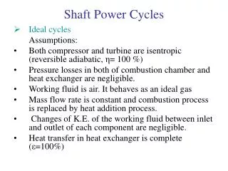
RANKINE CYCLE: THE IDEAL CYCLE FOR VAPOR POWER CYCLES Many of the impracticalities associated with the Carnot cycle can be eliminated by superheating the steam in the boiler and condensing it completely in the condenser. The cycle that results is the Rankine cycle, which is the ideal cycle for vapor power plants. The ideal Rankine cycle does not involve any internal irreversibilities. The simple ideal Rankine cycle.
Energy Analysis of the Ideal Rankine Cycle Steady-flow energy equation The efficiency of power plants in the U.S. is often expressed in terms of heat rate, which is the amount of heat supplied, in Btu’s, to generate 1 kWh of electricity. The thermal efficiency can be interpreted as the ratio of the area enclosed by the cycle on a T-s diagram to the area under the heat-addition process.
HOW CAN WE INCREASE THE EFFICIENCY OF THE RANKINE CYCLE? The basic idea behind all the modifications to increase the thermal efficiency of a power cycle is the same: Increase the average temperature at which heat is transferred to the working fluid in the boiler, or decrease the average temperature at which heat is rejected from the working fluid in the condenser. Lowering the Condenser Pressure (Lowers Tlow,avg) To take advantage of the increased efficiencies at low pressures, the condensers of steam power plants usually operate well below the atmospheric pressure. There is a lower limit to this pressure depending on the temperature of the cooling medium Side effect: Lowering the condenser pressure increases the moisture content of the steam at the final stages of the turbine. The effect of lowering the condenser pressure on the ideal Rankine cycle.
Superheating the Steam to High Temperatures (Increases Thigh,avg) Both the net work and heat input increase as a result of superheating the steam to a higher temperature. The overall effect is an increase in thermal efficiency since the average temperature at which heat is added increases. Superheating to higher temperatures decreases the moisture content of the steam at the turbine exit, which is desirable. The temperature is limited by metallurgical considerations. Presently the highest steam temperature allowed at the turbine inlet is about 620°C. The effect of superheating the steam to higher temperatures on the ideal Rankine cycle.
Today many modern steam power plants operate at supercritical pressures (P > 22.06 MPa) and have thermal efficiencies of about 40% for fossil-fuel plants and 34% for nuclear plants. A supercritical Rankine cycle. Increasing the Boiler Pressure (Increases Thigh,avg) For a fixed turbine inlet temperature, the cycle shifts to the left and the moisture content of steam at the turbine exit increases. This side effect can be corrected by reheating the steam. The effect of increasing the boiler pressure on the ideal Rankine cycle.
THE IDEAL REHEAT RANKINE CYCLE How can we take advantage of the increased efficiencies at higher boiler pressures without facing the problem of excessive moisture at the final stages of the turbine? 1. Superheat the steam to very high temperatures. It is limited metallurgically. 2. Expand the steam in the turbine in two stages, and reheat it in between (reheat) The ideal reheat Rankine cycle.
The single reheat in a modern power plant improves the cycle efficiency by 4 to 5% by increasing the average temperature at which heat is transferred to the steam. The average temperature during the reheat process can be increased by increasing the number of expansion and reheat stages. As the number of stages is increased, the expansion and reheat processes approach an isothermal process at the maximum temperature. The use of more than two reheat stages is not practical. The theoretical improvement in efficiency from the second reheat is about half of that which results from a single reheat. The reheat temperatures are very close or equal to the turbine inlet temperature. The optimum reheat pressure is about one-fourth of the maximum cycle pressure. The average temperature at which heat is transferred during reheating increases as the number of reheat stages is increased.
THE IDEAL REGENERATIVE RANKINE CYCLE Heat is transferred to the working fluid during process 2-2 at a relatively low temperature. This lowers the average heat-addition temperature and thus the cycle efficiency. In steam power plants, steam is extracted from the turbine at various points. This steam, which could have produced more work by expanding further in the turbine, is used to heat the feedwater instead. The device where the feedwater is heated by regeneration is called a regenerator, or a feedwater heater (FWH). A feedwater heater is basically a heat exchanger where heat is transferred from the steam to the feedwater either by mixing the two fluid streams (open feedwater heaters) or without mixing them (closed feedwater heaters). The first part of the heat-addition process in the boiler takes place at relatively low temperatures.
Open Feedwater Heaters An open(or direct-contact) feedwater heateris basically a mixing chamber, where the steam extracted from the turbine mixes with the feedwater exiting the pump. Ideally, the mixture leaves the heater as a saturated liquid at the heater pressure. The ideal regenerative Rankine cycle with an open feedwater heater.
Closed Feedwater Heaters Another type of feedwater heater frequently used in steam power plants is the closed feedwater heater, in which heat is transferred from the extracted steam to the feedwater without any mixing taking place. The two streams now can be at different pressures, since they do not mix. The ideal regenerative Rankine cycle with a closed feedwater heater.
REFRIGERATORS AND HEAT PUMPS The transfer of heat from a low-temperature region to a high-temperature one requires special devices called refrigerators. Refrigerators and heat pumps are essentially the same devices; they differ in their objectives only. for fixed values of QL and QH The objective of a refrigerator is to remove heat (QL) from the cold medium; the objective of a heat pump is to supply heat (QH) to a warm medium.
THE REVERSED CARNOT CYCLE The reversed Carnot cycle is the most efficient refrigeration cycle operating between TL and TH. However, it is not a suitable model for refrigeration cycles since processes 2-3 and 4-1 are not practical because Process 2-3 involves the compression of a liquid–vapor mixture, which requires a compressor that will handle two phases, and process 4-1 involves the expansion of high-moisture-content refrigerant in a turbine. Both COPs increase as the difference between the two temperatures decreases, that is, as TLrises or THfalls. Schematic of a Carnot refrigerator and T-s diagram of the reversed Carnot cycle.
THE IDEAL VAPOR-COMPRESSION REFRIGERATION CYCLE The vapor-compression refrigeration cycle is the ideal model for refrigeration systems. Unlike the reversed Carnot cycle, the refrigerant is vaporized completely before it is compressed and the turbine is replaced with a throttling device. This is the most widely used cycle for refrigerators, A-C systems, and heat pumps. Schematic and T-s diagram for the ideal vapor-compression refrigeration cycle.
The ideal vapor-compression refrigeration cycle involves an irreversible (throttling) process to make it a more realistic model for the actual systems. Replacing the expansion valve by a turbine is not practical since the added benefits cannot justify the added cost and complexity. Steady-flow energy balance An ordinary household refrigerator. The P-h diagram of an ideal vapor-compression refrigeration cycle.
ACTUAL VAPOR-COMPRESSION REFRIGERATION CYCLE An actual vapor-compression refrigeration cycle differs from the ideal one in several ways, owing mostly to the irreversibilities that occur in various components, mainly due to fluid friction (causes pressure drops) and heat transfer to or from the surroundings. The COP decreases as a result of irreversibilities. DIFFERENCES Non-isentropic compression Superheated vapor at evaporator exit Subcooled liquid at condenser exit Pressure drops in condenser and evaporator Schematic and T-s diagram for the actual vapor-compression refrigeration cycle.
Cascade Refrigeration Systems Some industrial applications require moderately low temperatures, and the temperature range they involve may be too large for a single vapor-compression refrigeration cycle to be practical. The solution is cascading. Cascading improves the COP of a refrigeration system. Some systems use three or four stages of cascading. A two-stage cascade refrigeration system with the same refrigerant in both stages.