Download
1 / 20
200 likes | 350 Vues
In some cases where the simulation circuit would get to big or cluttered with details it is wise to use a hierarchal approach in a simulation. The hierarchal approach allows the user to bury details into subcircuits and build commonly

E N D
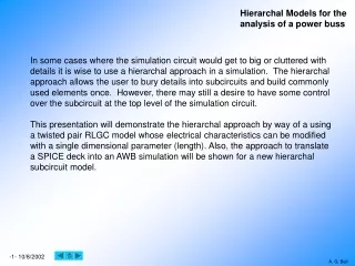
In some cases where the simulation circuit would get to big or cluttered with details it is wise to use a hierarchal approach in a simulation. The hierarchal approach allows the user to bury details into subcircuits and build commonly used elements once. However, there may still a desire to have some control over the subcircuit at the top level of the simulation circuit. This presentation will demonstrate the hierarchal approach by way of a using a twisted pair RLGC model whose electrical characteristics can be modified with a single dimensional parameter (length). Also, the approach to translate a SPICE deck into an AWB simulation will be shown for a new hierarchal subcircuit model.
We would like to simulate the power buss of a system and include detailed models of the wires and subsystems. To do this it makes sense to build hierarchal models for each wire and subsystem and then interconnect them in a hierarchal simulation. The wire model will use the RLGC lossy lumped element twisted pair model with a slight modification for grounding and will change electrical characteristics as a function of wire length. One subsystem model which has been supplied to us as an Intusoft SPICE model will be translated into the proper AWB format and integrated into the hierarchal simulation
We have reviewed the literature and found a model for a twisted pair. This MathCAD program is used to calculate the R, L and C values for the wire we would like to model. Using this program the user could determine new R, L and C values based upon other wire types. Or the model could also be changes to pass these wire parameters. Build our model and compare our electrical characteristic to the calculated values. In our case the temperature coefficient of the wire will be ignored, i.e. temp will be set equal to 20°C.
A subcircuit model is built and shows that for a 1 foot length of wire the simulation results match the expected results. equals 2X for two wires A test circuit is built to test the model. In this case the R, L and C will be measured as well as the characteristic impedance Zo As can be seen there is a good match between the MathCAD program and AWB simulation results. The model is validated and can be used for simulations.
Now we will build the hierarchal model of the wire. Step 1: Draw the base schematic for the RLGC model and define each value as function of R, L and C.
This is the completed schematic model we will use for the twisted pair RLGC model. We also added 1000MEG resistors to insure that there is a DC path to ground for all nodes. Next we will need to add the variable table…
Step 2: Add the variable table and define the R, L and C values as functions of wire length. Other variables are used to define R, L and C but only length will be passed through the body.
Here is the completed schematic model with the variable table. Next we will need to build the body …
Step 3: Build the body for the part. Step 4: Add dots to the body where you want connections. Step 5: Add signal names to the dots that match the schematic signal names.
Step 6: Add path and length as properties to the body at the origin of the symbol. Origin
Where, RO = bulk resistivity of copper (ohm-in) WD = wire diameter (in) ER = effective relative dielectric constant of medium between wire in this case the insulation is ETFE (2.5 to 2.6) S = separation between the wires (in) and R, L and C are calculated based upon length… And your done. This is an adaptation of the basic lumped element RLGC model which provides some minimum distributed impedances. G is not included. Schematic Only the values are shown. Body 1000Meg resistors added to model so all nodes would have a dc path to ground. R, L and C are all functions of length so the equations for each can be written as expressions where length is a variable attached to the body of the model. Length can then be passed through the body to modify the R, L and C values.
Schematic Body Once the base model is built it can be expanded in a hierarchal fashion to build more complicated models. In this case all the models used here are hierarchal. Now we will expand the base twisted pair model to mimic the cables used in the system. Imagine how complicated this schematic would be if it was drawn as a flat schematic hierarchal schematic
We were given a SPICE deck for one of the subsystems that we want to translate into AWB and place in our hierarchal simulations In this case a SPICE model exists that we want to import into our simulation. The model has a three page schematic. Also, we have discovered that the “limiter” does not translate into AWB directly because and the model for this stage must be converted into the AWB model. We will also need to define the inputs and outputs of our model. In this case we will pick VBAT as the input and IDC and I3 to be our outputs. We will also define ground as an I/O in our model. This is an Intusoft SPICE model of the buss power supply.
Page three of the Intusoft model. In this case the multiplier also does not convert to AWB so it must be replace with the AWB multiplier model.
The SPICE deck for the model must be dissected to determine to translate it into the AWB format. With the exception of the two circuit models that don’t translate directly we will also need to remove SPICE options and replace node names with node number which have not been used. A simple text editor can be used for this option. *BOOST NOM, IDC=40A *.NODESET V(VDCC)=0.3 *.NODESET V(44)=-2.0 *BOOST NOM, IDC=20A .NODESET V(VDCC)=0.5 .NODESET V(50)=-2.6 .NODESET V(zverr)=7.0 .IC V(VDCC)=0.3 V(44)=-2.5 *#op .OPTIONS itl1=1000 .OPTIONS gmin=10n reltol=0.01 rshunt=100meg VBAT 1 0 DC=21 RBAT 1 2 0.021 RHARNESS 2 3 0.004 L1 3 4 0.2NH RBATFL 4 5 0.01 CBAT 5 0 360UF D1x 4 Vevb2 _DBAT .MODEL _DBAT D BV=45 CJO=5.915n IBV=1 IS=924.7n M=0.3333 + RS=2.018m TT=417ps VJ=0.75 D2x 4 Vevb2 _DBAT D3x 4 Vevb2 _DBAT R4xx Vevb2 0 10K R5xx Vevb2 7 10K RBANK Zbus 15 0.062 BEVBOOST 7 Vevb2 V=V(Vevb2)*V(VDCC) I3 Zbus 0 DC=0 PULSE 0 8 100US 1US 1US 400US VIBOOST 8 9 DC=0 R6xx 9 10 1K R7xx 10 11 0.007 L2 11 Zbus 120UH D4x 9 10 _DMODBST .MODEL _DMODBST D BV=150 CJO=1.457n IBV=100u IS=7.5u + M=0.3333 N=2 RS=0.1m TT=123.3n VJ=0.75 R8xx 9 13 1K R9xx 13 14 0.007 L3 14 Zbus 120UH D5 9 13 _DMODBST R10x 9 16 1K R11x 16 17 0.007 L4 17 Zbus 120UH D6 9 16 _DMODBST Cbank 15 18 621u LBANK 18 0 10nh LTRAP Zbus 20 2.6uh CTRAP 20 21 30uf RTRAP 21 0 0.041 RBUSFL Zbus 19 0.0083 LBUSFL 19 22 3.3nh CBUSFL 22 0 0.3uf RMINLOAD Zbus 0 100 IDC Zbus 0 DC=20 EEA 24 0 34 31 300K RZBIAS 69 23 2.89k D7 0 23 DN827A .MODEL DN827A D BV=6.153 CJO=100P IBV=7.5M IS=4.07F M=.33 + N=1 RS=6.54 TT=55.1N VJ=.75 CREF 23 0 0.1uf X1x 24 25 LIMIT { K=1 PLIM=23 NLIM=0 } .SUBCKT LIMIT 1 2 {K=??? PLIM=??? NLIM=???} *Connections: In Out *Parameters: K Gain, PLIM Positive rail in Volts, NLIM Negative rail in Volts RIN 1 0 1E12 E1 3 0 0 1 {K} RC1 2 4 1MEG C1 2 4 1F IC=0 R1 3 4 1MEG E2 2 0 0 4 1E6 *DIODES WILL HAVE .0597V DROP AT 10V INPUT FOR GAIN=1 *IDIODE = IS*EXP(.597/.O26) VN 5 2 {NLIM-.0597} DN 4 5 DN .MODEL DN D(IS=1E-12 N=.14319) VP 2 6 {PLIM-.0597} DP 6 4 DN .ENDS R17 25 26 9k D8 26 27 DN4148 .MODEL DN4148 D BV=100V CJO=4PF IS=7E-09 M=.45 N=2 RS=.8 + TT=6E-09 VJ=.6V Q1 30 27 Zverr QN2222A .MODEL QN2222A NPN BF=205 BR=4 CJC=15.2P CJE=29.5P IKF=.5 + IKR=.225 IS=81.1F ISE=10.6P NE=2 NF=1 NR=1 RB=1.37 RC=.137 + RE=.343 TF=397P TR=85N VAF=113 VAR=24 XTB=1.5 R18 27 Zverr 5K RQOUP Zverr 28 2420 RQOLOW 28 0 804 R21 30 69 395
You will also need to pay attention to the length of the lines in the SPICE deck. The “+” sign is used to concatenate lines. RFBK 28 32 11.6k CFBK 32 31 6000pf R23 31 23 15.5k VBODE 33 69 AC=0 RUPPER 33 34 50.083k RLOW 34 0 14K LJENSEN 69 35 2.36m RL_F 35 ZJEN 1.3 R27 ZJEN 0 311 CJENSEN ZJEN 0 18uf CSEC1 ZJEN 37 0.55uf RSEC2 37 0 30 CSEC2 ZJEN 38 4.8uf RSEC1 38 0 62 E12V 39 0 ZJEN 0 0.4726 E_4V 0 42 ZJEN 0 0.178 R30 39 0 10K D12V 39 40 DN4148 R12VFL 40 41 30 C12V 41 0 10uf D4_RECT 43 42 DN4148 R_4FL 43 44 10 C_4 44 0 8.2uf BFIFBK 45 44 I=I(VIBOOST)*I(VIDCC)*0.667m R33 45 44 1K DIRECT 46 45 DN4148 R34 46 44 100 CI1 46 44 0.82uf RIDFFS 46 47 15K CI2 47 44 0.068uf RQAMP2E 44 50 4.75K R37 46 48 1180 DIOFFS 47 48 DN4148 RISUM 47 49 15K QDCCAMP2 Zdivb 49 50 QN2222A D 49 0 _DCLAMP .MODEL _DCLAMP D CJO=1E-18 EG=0.1 IBV=100n IS=1u + M=0.3333 RS=100u TT=50ps VJ=0.75 XTI=0 QDCCAMP1 49 51 52 QN2907A .MODEL QN2907A PNP BF=154 BR=4 CJC=20.8P CJE=15.6P + IKR=.21 IS=381F ISE=15.3P NE=2 NF=1 NR=1 RB=2.21 + RE=.552 TF=636P TR=63.7N VAF=139 VAR=20 XTB=1.5 + IKF=.14 RC=.221 RDCNEG 44 Zverr 3k RDCIN Zverr 51 15K RDCCAC1 52 53 30K CDCC1 53 55 1240pf RDCCAC2 52 54 30K C15 54 55 780pf RDCCBIAS 55 52 15K RDCCQ2C 55 Zdivb 22K R2VA 41 55 200 D11VZ 0 55 _D14_mod .MODEL _D14_mod D BV=10.94 CJO=44.2P + IBV=1M IS=2.07N M=.33 + N=1 RS=64.1 TT=50.1N VJ=1 R46 Zdivo 67 100 QRAMP Zdiva 57 60 QN2907A D15 58 51 DN4148 R2VB 55 57 200 R5V 57 58 500 R3V 58 0 300 RRAMP2 60 61 10.5K RRAMP28V ZJEN 60 89K DRAMP 61 41 DN4148 I12V 41 0 DC=0.004 RRAMPMAX Zdiva 63 13.889K RDIV1 63 Zdivd 10 RDIV2 Zdivd 0 100 RRAMP1 61 65 28.6K RBUFL 65 Vevb2 1K VRMP0 0 63 DC=0.7 CBUFL 65 0 0.47uf BFIBATT Vevb2 0 I=I(VIBOOST)*I(VIDCC) R71 67 0 10MEG GDCCLMP 0 72 73 0 100 D2 0 72 _DCLAMP D3 72 86 _DCLAMP B5 7 8 V=0.00367*I(VIBOOST)+0.00833*I(VIBOOST)*I(VIDCC) V8 69 Zbus AC=0 EVNUM 71 0 Zdiva Zdivb 1 R1x Zdiva 0 1MEG R2x Zdivb 0 1MEG EVDNOM 74 0 Zdiva Zdivd 1 R3x Zdiva 0 1MEG R4x Zdivd 0 1MEG R5x 71 77 1K R6x 77 78 1K R7x 78 0 1MEG EGDIV 79 0 0 77 1E4 X1 80 74 78 MUL { K=1 } .SUBCKT MUL 1 2 3 {K=???} *Connections: In1 In2 Out *Parameters: K Gain B1 3 0 V = V(1) * V(2) * {K} .ENDS R8x 74 0 1 R9x 79 0 1 R10 79 80 1K EDIVOUT Zdivo 0 0 80 1 D19 0 67 _DCLAMP R12 Zdivo 0 1MEG RC3 86 87 100 D20 67 68 _DCLAMP V6 68 0 DC=10 VIDCC 87 0 DC=0 R4 86 0 1.010101 D4 72 88 _DCLAMP VDCCLAMP 88 0 DC=100 ECLDC VDCC 0 86 0 0.01 Izin 0 Zbus AC=1 R6 VDCC 0 1MEG E10 59 0 67 0 100 R83 59 75 50 T1 75 0 76 0 ZO=50 TD=1U R84 76 0 50 D22 76 81 _DCLAMP R85 59 82 50 R86 82 0 50 D23 82 81 _DCLAMP E11 73 0 81 85 0.02 R87 81 0 10MEG D24 0 85 _DCLAMP I5 85 0 DC=0.001 I6 81 0 DC=0.001 .END
start DEVICE_INFO MODEL_TYPE=570 SYMBOL_NAME=newpru end DEVICE_INFO start TEXT PRE-ANALYSIS RAW_SPICE :=" *VBAT 1 0 DC=21 RBAT 1 2 0.021 RHARNESS 2 3 0.004 L1 3 4 0.2NH RBATFL 4 5 0.01 CBAT 5 999 360UF D1x 4 100 _DBAT .MODEL _DBAT D BV=45 CJO=5.915n IBV=1 IS=924.7n M=0.3333 + RS=2.018m TT=417ps VJ=0.75 . . . I5 85 999 DC=0.001 I6 81 999 DC=0.001 * VA=1 * VEVB2=100 * ZVERR=200 * ZJEN=300 * ZBUS=400 * VDCC=500 * VIDCC=600 * Zdiva=700 * Zdivb=710 * Zdivd=720 * Zdivo=730 * GND=999 " end TEXT PRE-ANALYSIS start NODES TERM(VA)=1 TERM(ZBUS)=400 TERM(GND)=999 end NODES You can add comments to your SPICE deck by using the “*” at the start of a line… Build the body to match the SPICE deck. Notice that the names on the body match the terminal names used on the body.
Step 2: Add the following to the end of the SPICE deck… " end TEXT PRE-ANALYSIS start NODES TERM(VA)=1 TERM(ZBUS)=400 TERM(GND)=999 end NODES Term are based on the I/O you have chosen. Step 1: Add the following to the start of the SPICE deck… start DEVICE_INFO MODEL_TYPE=570 SYMBOL_NAME=newpru {you define this} end DEVICE_INFO start TEXT PRE-ANALYSIS RAW_SPICE :=“ (insert the SPICE deck here) Step 3: Move SPICE deck to UNIX side … Will need to do the DOS2UNIX command to eliminate line feeds Step 4: Build model body … Test you new model and your done!
Now we can simulate a very large design without having a complicated flat schematic to manage. Plus we have the option to change the wire length on any cable to determine how the performance of the system will change. partial hierarchal schematic