Download
1 / 77
830 likes | 1.42k Vues
Debanjan Das Amrita Mukherjee Chethan Kumar Gaddam Ganesh Rahul Bhimanapati. PLASMA GASIFICATION FOR VOC DESTRUCTION . Problem Statement.

E N D
DebanjanDas Amrita Mukherjee Chethan Kumar Gaddam Ganesh Rahul Bhimanapati PLASMA GASIFICATION FOR VOC DESTRUCTION
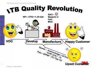
Problem Statement • By using a non-thermal plasma in conjunction with catalytic heterogeneous chemistry and optimization of energy coupling into the plasma, economic analyses are expected to show that a more energy efficient (and hence cost effective) method based upon plasma-remediation can be used for VOC cleanup. • Economic and technical comparison of traditional incineration based VOC removal system and our proposed device based on a case study approach. • Goal: To design a plasma-based system for volatile organic destruction.
Concept Map Continuous parameters evaluation (Energy yield, g value, etc) Economic Trade Off between NTP systems Selectivity Regenerability Energy & Economic Analysis Catalysts Problem Statement System Design Chemistry Reaction Mechanism & Pathways Choice of Reactor Spectroscopic Evaluations Electrodes
VOC • Volatile Organic Compounds (VOCs) are comprised of a variety of organic species that are readily reactive in the atmosphere. • Major source of VOCs include cleaning solutions, waxes, disinfectants, stored fuels, paint strippers and other solvents, and their emission from automobiles, paint industries, tanneries, petroleum distilleries, timber, and paper industries. • Examples: hydrocarbons, PAHs, Chlorinated Aromatic Compounds, etc. http://www.epa.gov/iaq/voc.html
VOC • Volatile organic compounds are bad for the environment and human health. Therein many rules are regulated by the U.S. EPA but their control requires either catalytic destruction or downstream incineration. Both process contribute to product cost without adding value. Notably both approaches are thermally based and as such, are energy intensive.
Plasma • Plasma is a collection of free moving electrons and ions that are usually formed upon ionization of gases. • To create plasma, energy is required which may be of various forms: thermal, electrical or light energy. • Electrons in plasma may be in thermodynamic equilibrium with the surrounding gas. Such plasma is defined as equilibrium plasma. Usually such plasma is at a very high temperature, and is often known as Thermal Plasma. • In industrial processes, the type of plasma used is mainly non-equilibriumplasma where the electrons are not in thermodynamic equilibrium with the surrounding medium. In such cases, the electrons are usually at a much higher energy level than the medium. Normally such plasma is at a lower temperature and usually generated from electrical energy. Such plasma is also known as Non-thermal Plasma
Non-Thermal Plasma What Is Non-Thermal Plasma? • Everyone is familiar with static electricity that occurs when reaching for a metal door handle after walking across a carpet. • In technical terms, static electricity is the discharge of electricity that occurs when the potential (that is, voltage) exceeds the insulating effect of the air gap between your finger and the door handle. Non-thermal plasma uses a reactor that utilizes a similar effect. • The reactor consists of two electrodes (one electrode is in the form of a metal pipe, and the other electrode is a metal wire that runs down the middle of the pipe) separated by a void space that is lined with a dielectric material and is filled with glass beads. This type of reactor is called Dielectric-Barrier Discharge (DBD).
Non-Thermal Plasma • Emissions flow inside of the pipe. A phenomenon occurs when the voltage through the beads exceeds the insulating effect of the beads and millions of micro-discharges occur. • The duration of these discharges is measured in nano-seconds. • The individual discharges cannot be seen with the human eye, but the overall effect produces a silent glow. This effect will only occur when the power source is alternating current (AC). DBD cannot be induced with direct current (DC) power because the capacitive coupling of the dielectric necessitates an AC field.
Non-Thermal Plasma • In this environment, in addition to electrons flying about, atoms are being separated from their molecules to become free radicals. • Since free radicals are highly reactive, they quickly recombine with other atoms and/or molecules to form new compounds. • Using oxygen as an example, the normal state of oxygen is a molecule containing two oxygen atoms. Thus, it is written as O2. • In a DBD field, the oxygen molecules splits into two atoms of oxygen, O + and O +. The elemental oxygen radical, being very reactive, will form ozone, O3, when the radical oxygen atom reacts with a normal molecule of oxygen (O2).
1 Chemistry Summary of spectral transitions, chemistry equations
Electron Impact Ionization • Electron ionization (EI, formerly known as electron impact) is an ionization method in which energetic electrons interact with gas phase atoms or molecules to produce ions. • The following gas phase reaction describes the electron ionization process: M + e- → M+● + 2e- • where M is the analyte molecule being ionized, e− is the electron and M+• is the resulting ion. http://en.wikipedia.org/wiki/Electron_ionization
Electron Impact Processes Electron-impact dissociation of molecular oxygen produces the ground state atomic oxygen O(3P) and excited atomic O(1D): Electron Attachment Direct dissociation by electron impact Dissociation by Electron impact ionization Electron-impact dissociative ionization Effects of Oxygen and Water Vapor on Volatile Organic Compounds Decomposition Using Gliding Arc Gas Discharge Plasma Chem Plasma Process (2007) 27:546–558
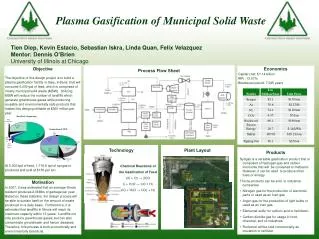
Plant • The Oklahoma Air Logistics Center at Tinker Air Force Base in Midwest City, Oklahoma requires a control technology to reduce the emission of Volatile Organic Compounds (VOCs) from its paint booths, to obtain compliance with Title III of the US Clean Air Act 1990 and MACT (Maximum Achievable Control Technology). • Tinker would like to switch to high pigment paint but the higher VOC emissions results in the need for a control technology. • There are of 42 paint booths that operate 5 – 6 hours a day. The entire painting operation is performed in 15 minute intervals. • Hence, Tinker needs a control technology that can be turned on and off when required and instantly operate to full capacity.
Emission Inventory • The VOC emission inventory obtained from Tinker is shown in Table . The inventory lists the major chemicals emitted from paint booth B2121 and their calculated emission rate in 2001
Destruction of Toluene Alternative Methods of Toluene Destruction • Toluene can be removed by adsorption using activated carbon, thermal oxidation and incineration, bio-filtration and plasma destruction. • Carbon adsorption is cheap and effective (90%) compared with other methods but the presence of high concentrations of ketones and alcohols can causes fire in a carbon bed. • Finally, the destruction VOCs using an alternate current plasma reactor is effective (>95% Destruction Efficiency) and potentially less expensive than othercompeting technologies.
Destruction of Toluene • Numerous reactions may take place in a DBD plasma reactor that can lead to the formation of active species capable of reacting with pollutant molecules. • These species react with pollutant molecules, which can result in near complete oxidation of hydrocarbons into CO, CO2, H2O and conversion of species such as Cl, S and NO into HCl, Cl2, SO2, H2SO4, HNO3. • If the concentration of the active species is high enough to initiate the destruction reaction, the pollutant concentration decreases.
Destruction of Toluene • The complete reaction chemistry is extremely complicated. The reactant molecules are known to undergo a series of intricate intermediate reactions before breaking down completely destroying into combustion products. • Due to the complexities of these mechanisms for pollutant destruction in DBD plasma reactors, additional research needs to be done in the mechanism of the reaction. • The destruction of toluene in a plasma reactor occurs through oxidation. A possible free radical mechanism for the oxidation of toluene in the reactor is discussed below. • Toluene can either react with the atmospheric oxygen or the hydroxyl radical once a mixture of radicals is formed in the reactor. The following reactions show one possible mechanism of toluene destruction in the DBD plasma reactor.
Decomposition Toluene The toluene decomposition process mainly includes the following reactions: Energetic electron induced decomposition reactions: C7H8+e → C6H5 + CH3 + e C7H8 + e → C7H7 + H + e C7H8 + e → C5H6 + C2H2 + e C7H8 + e → C3H4 + C4H4 + e Dissociation rate coefficients can be obtained from the solution of Boltzmann equation for the electron energy distribution. Reactions between toluene and radicals: C7H8+ O → products K400 = 3.67 10-13cm3mol-1 s-1 C7H8 + OH →C7H7+ H2O K400= 1.14 10-12cm3 mol-1 s-1 Effects of Oxygen and Water Vapor on Volatile Organic Compounds Decomposition Using Gliding Arc Gas Discharge Plasma Chem Plasma Process (2007) 27:546–558
Decomposition of Toluene • The above figures show the variations of the toluene decomposition rate as a function of the oxygen volumetric fraction and RH: this reaction rate is markedly increasing from 36 to 85% when the oxygen density is increased in the treated gas. • It is also increasing by adding water vapor when the GA is working in dry nitrogen atmosphere. • By contrast, the toluene decomposition rate (*85%) is not obviously affected by the presence of water vapor in air atmosphere. Plasma Chem Plasma Process (2007) 27:546–558
FTIR Absorption Spectra • The toluene decomposition efficiency is strongly influenced by the presence of the O and OH radicals in the plasma region, the addition of oxygen and water vapor in the treated gas enhances the decomposition of this volatile organic compound. Plasma Chem Plasma Process (2007) 27:546–558
Spectroscopy tool • Here is a spectra of a carbonaceous compound. We can clearly identify the species that are present in the compound.
2 Reactor Design Comparing different types of plasma configurations, optimizing reactor performance
Dielectric Barrier Discharge Reactor • DBD: • Characterized by the presence of one or more insulating layers in the • current path between metal electrodes in addition to the discharge space • The discharge characteristics depend on the gas composition, type of dielectric material and operating conditions of voltage and frequency. • For air-like mixtures- short-lived filaments is dominant – microdischarges • For inert gases – glow-mode discharge is dominant – atmospheric pressure glow discharge (APGD) • The advantage of DBD over pulsed corona : • Simpler and cheaper power supply • Can be scaled up without difficulty. Plasma Process. Polym. 2004, 1, 91–110
Surface Discharge Reactor • Surface Barrier Discharge: • It is a type of dielectric barrier discharge. • The electrodes are embedded in the dielectric. • The plasma will be generated on the surface of dielectric • Advantage: • It can analyze solid sample better than DBD. Plasma Process. Polym. 2004, 1, 91–110
Pulsed Corona Reactor • Requires a pulse power supply with a fast voltage rising time of several tens of nanoseconds. • Pulse power reduces the energy consumption by a factor of 5. • The discharge mode is streamer mode. • Advantages: • The ionization zone spreads over the entire gap and that is favorable for large scale application. • Uses short width pulses, to minimize energy dissipation by ions. • By controlling pulse frequency , the volume of gas treated can be controlled Nonthermal Plasma Processing for Air-Pollution Control: A Historical Review, Current Issues, and Future Prospects Plasma Process. Polym. 2004, 1, 91–110
Capillary Plasma Discharge Concept Annular plasma reactor with cylindrical electrodes (1: aluminum bar electrode; 2: aluminum screen electrode; 3: dielectric material; 4: Pyrex glass body; 5: capillary; 6: gas inlet; 7: gas outlet; 8: power supply). Rectangular reactor with hollow pin capillary electrodes. The gas flows through the hollow pins, flow-through geometry (1: gas inlet; 2: gas outlet; 3: spacer; 4: dielectric material; 5: stainless steel hollow pins; 6: copper electrode; 7: capillary; 8: power supply). Destruction of hydrocarbons in non-thermal, ambient-pressure, capillary discharge plasmas International Journal of Mass Spectrometry 233 (2004) 305–315
Gliding Arc Concept Three main channels for VOCs decomposition are generally pointed out under non-thermal plasma conditions: (I) Dissociation of VOCs molecules by energetic electrons impact; (II) Reactions between VOCs molecules and ions; (III) Reactions between VOCs molecules and radicals. 1) The increase of oxygen concentration enhances the production of O radicals, but decreases the electron density in the discharge; 2) The addition of water vapor reduces the amount of electrons, suppresses the formation of O radicals but gives rise to the formation of OH radicals. Effects of Oxygen and Water Vapor on Volatile Organic Compounds Decomposition Using Gliding Arc Gas Discharge Plasma Chem Plasma Process (2007) 27:546–558
Packed-bed Reactor SALIENT FEATURES: • Ferroelectric pellet packed-bed Reactors were first developed as a type of ESP and were found to be effective not only in collecting particles (99.99%removal) but also in destroying yeast cells. • Developed for VOCs decomposition, odor removal, and CO2 reduction. • The mostly widely used ferroelectric material is barium titanate (BaTiO3). Others include Mg2TiO4, CaTiO3, SrTiO3, and PbTiO3. ADVANTAGES: • Uniform distribution of gas flow and the discharge in the reactor. • Modification of the reactor to include a catalyst is very easy. DISADVANTAGES: Pressure Drop, proper reactor design-energy efficiency. Plasma Process. Polym. 2004, 1, 91–110
Catalyst 3 • Comparing different catalysts, integrating catalyst in to the non-thermal plasma reactor
TYPES OF CATALYST SYSTEMS • ADVANTAGES OF CATALYST IN THE SYSTEM: • The existence of abundant short-lived active species (i.e., excited species, radicals, and positive/negative ions)-Changes the status of the gas phase reactants for the occurrence of plasma discharge on catalyst surface • voltage potential and a current flow across the catalyst-(Affects the physical and chemical Properties), higher residence time • Reduces the unwanted or harmful byproducts i.e., CO, NOx, O3 by selectivity of the catalyst
SPC over TPC & MPC • SPC- Single stage Plasma Catalysis • TPC- Two stage Plasma Catalysis • MPC- Multistage Plasma Catalysis • Ions and electronically excited species would have de-excited before they reach the catalyst surface. • The internal energy of the species in rotational state is not sufficient to induce further reactions. • Although the internal energy of vibrationallyexcited species is not enough to induce plasma chemistry reactions, they are the active species produced in plasma with the minimum internal energy to improve catalytic reactions. • Radicals generally show a much higher sticking coefficient for chemisorption, an essential step of catalytic reactions. • Deactivation of catalyst in the case of TPC and MPC is easier.
Catalyst Work (a) (b) (c) Image of plasma Discharge in hybrid reactors packed with BT Conventional Reactor BT> Catalyst (in r) BT< Catalyst (in r) A.Ogata Et. Al. J Applied Catalysis B: Environmental 46 (2003) 87-93
Particle Size Selection MS-3A- BaTiO3<Catalyst Particles MS-13X- BaTiO3> Catalyst Particles Temperature Programmed Desorption Under Plasma Discharge MS-3A- BaTiO3<Catalyst Particles MS-13X- BaTiO3> Catalyst Particles A.Ogata Et. Al. J Applied Catalysis B: Environmental 46 (2003) 87-93
Selection of Packing material A.Ogata Et. Al. J Applied Catalysis B: Environmental 46 (2003) 87-93
SPC PERFORMANCE ENVIRONMENTAL SCIENCE & TECHNOLOGY / VOL. 43, NO. 7, 2009
SPC PERFORMANCE ENVIRONMENTAL SCIENCE & TECHNOLOGY / VOL. 43, NO. 7, 2009
SPC PERFORMANCE ENVIRONMENTAL SCIENCE & TECHNOLOGY / VOL. 43, NO. 7, 2009
ASSUMPTIONS • The porosity(Ɛ) was calculated to be 0.733 assuming there are 5 particles in a cross section of 10mmX 2mm section of the experimental setup. We assume the scaled reactor is also having the same porosity. • The density(ρ) of the inlet gas was assumed to be 1.251 g/L ( Same as that of air). • The viscosity(µ) of the inlet gas was assumed to be .01781x10-2 g/(cc.sec). • The flow in the lab scale reactor was laminar flow which is assumed to be the same in the modeled reactor. • All the particles are assumed to be perfect spheres. Hence sphericity (φs) is 1. • The target gas flow rate is 2000 L/min.
CALCULATIONS • EXPERIMENTAL SETUP: Volume of the reactor (V)=(∏/4)*(L)*(do2-di2) =31415.926 mm3 =31.415cm3 Porosity (Ɛ) =1-{(vol. fraction of spheres)} = 1-{(n*4*∏*(0.2)3)/(3*31.415)} =.733 Reynolds Number = Rep={(ρ*Vs*Dp* φs2)/[µ*(1-Ɛ)]} ={[1.251*(.2/60)*(1/25.1327)*.2*1]/(.01781*10-2*(1-.733)} =0.6978 = Laminar flow
CALCULATIONS • From Korenzy-Carmen Equation Superficial velocity=µo= (Volumetric flow rate)/(Effective cross sectional area) =(.2/60*25.1327) cm/sec (∆P/L)= {[(150*µ*µo*(1-Ɛ)2]/[Dp* φs*Ɛ3]} = {[150*.01781*10-2*.2*(1- .733)2]/[.2*60*25.1327*.7333]} =1.602*10-2 g/s
CALCULATIONS • Reynolds Number = Rep={(ρ*Vs*Dp* φs2)/[µ*(1-Ɛ)]} ={(1.251*2000*.2*1)/[60*.01781*10-2 *∏*re2*(1-.733)]} =55854.9/re2 • From Korenzy-Carmen Equation (∆P/L)= {[(150*µ*µo*(1-Ɛ)2]/[Dp* φs*Ɛ3]} = {[150*.01781*10-2*2000*103*(1- .733)2]/[.2*100*60*∏*re2*.7332]} (∆P/L )=256.675/r2 The pressure drop across the bed is assumed to be increasing as the same rate as that of the flow rate because of the increasing in the packing material in the reactor.
CALCULATIONS Hence, Re2= 1.603*L From iterative calculations, the consideration for length is chosen to be 200 cm and the effective radius was Re2=320.24 Ro2-Ri2=320.24 From Solver which is run in excel, we get the radii as 30 cm and 24 cm (approximated to the next number and decimals are neglected)
SCALED UP DESIGN OF PLASMA REACTOR 60 cm 48 cm 200 cm 300 cm
SCHEMATIC OF EXPERIMENTAL SETUP Power meter F C U N2 CMSPS GC Benzene Transformer F C U Auto sampler Scrubber Mixing Tube Plasma Reactor F C U Water OES Temperature Control F C U O2 TERMS: F C U- Flow Control Unit CMSPS-Control Mode Switching Power Supply O E S- Optical Emission Spectrometer