Download
1 / 36
400 likes | 608 Vues
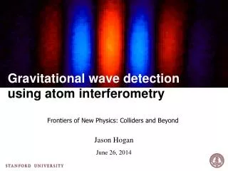
Prospects for gravitational wave detection with atom interferometry. Seoul National University Seoul, Korea. Jason Hogan Stanford University January 17, 2013. Topics. Atom interferometry in a 10 meter tower. Gravitational wave detection with atoms. Cold Atom Inertial Sensors.

E N D
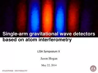
Prospects for gravitational wave detection with atom interferometry Seoul National University Seoul, Korea Jason Hogan Stanford University January 17, 2013
Topics Atom interferometry in a 10 meter tower Gravitational wave detection with atoms
Cold Atom Inertial Sensors Cold atom sensors: • Laser cooling; ~108 atoms, ~uK (no cryogenics) • Atom is freely falling (inertial test mass) • Lasers measures motion of atom relative to sensor case • Accelerometers, gravimeters, gyroscopes, gradiometers Technology evolution: AOSense commercial AI gravimeter (2011) AI gyroscope (1997) AI compact gyroscope (2008)
Light Pulse Atom Interferometry • Vertical atomic fountain • Atom is freely falling • Lasers pulses are atom beamsplitters & mirrors • pulse sequence F=4 Interior view F=3
10 m Accelerometer Sensitivity 10 m atom drop tower 2T~ 2.3 s K eff= 2k Shot noise limited detection @ 107 atoms per shot: rad (~ 1 month) State of the art: = 102k “LMT” beamsplitters with [S Chiow et al., Phys. Rev. Lett. 107, 130403 (2011).]
Atom Interferometry Design Goal: 10-15g Test of the Equivalence Principle 2T = 2.3 s: Images of Interferometry t = T: Image at apex F=2 F=1 1 cm ≈ 4 mm/s 1.5 cm F=1 ~ 10 m F=2 (pushed) 2.3 s
Apparatus • Ultracold atom source • >106 at 50 nK • Optical Lattice Launch • 13.1 m/s with 2372 photon recoils to 9 m • Atom Interferometry • 2 cm 1/e2 radial waist • 500 mW total power • Dyanmicnrad control of laser angle with precision piezo-actuated stage • Detection • Spatially-resolved fluorescence imaging • Two CCD cameras on perpendicular lines of sight
Beam Angle Phase Phase imprinted by beam angle (small ): Position: g
Coriolis Phase Phase imprinted by beam angle (small ): Uniform Rotation Rate Coriolis: Coriolis Effect Gustavson et al. PRL 78, 1997 McGuirk et al. PRA 65, 2001 Hogan et al. Enrico Fermi Proceedings, 2009 Lan et al. PRL 108, 2012
Coriolis Phase Phase imprinted by beam angle (small): Uniform Rotation Rate Coriolis: Coriolis Compensation Gustavson et al. PRL 78, 1997 McGuirk et al. PRA 65, 2001 Hogan et al. Enrico Fermi Proceedings, 2009 Lan et al. PRL 108, 2012
Rotation Compensation System • < 1 nrad measured precision • ~ 1 nrad repeatability • Piezoresistive position sensors • Rigidly anchored to quiet floor In-vacuum nanopositioning stage & mirror mirror nanopositioner (x3) Coarse alignment Anchor plate
Single-shot Phase & Contrast 60 μrad misalignment at final pulse F = 2 (pushed) F = 1 F = 1 g g F = 2 (pushed) 1 cm 1 cm ≈ 4 mm/s
Single-shot Phase & Contrast 60 μrad misalignment at final pulse F = 2 (pushed) F = 1 F = 1 g g F = 2 (pushed) 1 cm 1 cm ≈ 4 mm/s
Single-shot Phase & Contrast 60 μrad misalignment at final pulse F = 2 (pushed) F = 1 F = 1 g g F = 2 (pushed) 1 cm 1 cm ≈ 4 mm/s
Single-shot Phase & Contrast 60 μrad misalignment at final pulse F = 2 (pushed) F = 1 F = 1 g g F = 2 (pushed) 1 cm 1 cm ≈ 4 mm/s
Spatial Frequency vs Phase Shear θ (μrad) Spatial Fringes Beam angle phase: Fringe spatial frequency: 80 40 0 -40 -80 + correction for drift time to imaging Coriolis Compensated
Application: Gyrocompassing Beam Angle + Coriolis Error: Precision: 20 mdeg Repeatability: ~ 1 mdeg Correction to axis: -0.93 deg True north: g
LMT Beamsplitters: Coherent Phase Amplification Large momentum transfer (LMT) beamsplitters – multiple laser interactions Each laser interaction adds a momentum recoil and imprints the laser’s phase LMT energy level diagram Example LMT interferometer Phase amplification factor N
High Contrast LMT Atom Interferometers Coming Next: LMT atom optics in 10 m tower ~1 m wavepacket separation 7 x 10-14 g / shot 70% contrast 18% contrast Chiow, PRL (2011)
Topics Atom interferometry in a 10 meter tower Gravitational wave detection with atoms
Gravitational Wave Detection Why consider atoms? Neutral atoms are excellent “test particles” (follow geodesics) Atom interferometry provides exquisite measurement of geodesic w.r.t. laser “ruler” (LMT phase amplification) Flexible operation modes (broadband, resonant detection) Single baseline configuration possible (e.g., only two satellites)
Gravitational Wave Phase Shift Signal Laser ranging an atom (or mirror) that is a distance L away: Position Acceleration Phase Shift: Relativistic Calculation:
Vibrations and Seismic Noise Atom test mass is inertially decoupled (freely falling); insensitive to vibration Atoms analogous to LIGOs mirrors However, the lasers vibrate Laser has phase noise Laser vibration and intrinsic phase noise are transferred to the atom’s phase via the light pulses.
Differential Measurement Light from the second laser is not exactly common • Light travel time delay is a source of noise • Single photon transitions avoid this problem
Terrestrial Configuration • Run two, widely separated interferometers using common lasers • Measure the differential phase shift Benefits: • Signal scales with length L ~ 1 km between interferometers (easily increased) • Common-mode rejection of seismic & phase noise Allows for a free fall time T ~ 1 s. (Maximally sensitive in the ~1 Hz band) (e.g., vertical mine shaft)
Gravity Gradient Noise Limit Seismic noise induced strain analysis for LIGO (Thorne and Hughes, PRD 58) . Allows for terrestrial gravitational wave detection down to ~ 0.3 Hz Seismic fluctuations give rise to Newtonian gravity gradients which can not be shielded.
Satellite Configuration Common interferometer laser 10 – 50 m 10 – 50 m L ~ 1000 km
Strain Sensitivity L=106 m baseline 100 ħk 10-4rad/Hz1/2 T =100 s 60 m booms Space-based atom GW detector could have science potential comparable to LISA Flexible atom optics allows for both “broadband” and “resonant” modes
Requirements Analysis to determine requirements on satellite jitter, laser pointing stability, atomic source stability, and orbit gravity gradients. J. Hogan et al., GRG 43, 7 (2011).
Laser frequency noise insensitive detector All previous interferometric GW detectors need multiple baselines or ultra stable lasers. • Long-lived single photon transitions (e.g. clock transition in Sr, Ca, Yb, etc.) • Atoms act as clocks, measuring the light travel time across the baseline (time in excited state). • GWs modulate the laser ranging distance. Excited state Laser noise is common arXiv:1206.0818
LMT with single photon transitions Example LMT beamsplitter (N = 3) • Interesting sensitivity requires Large Momentum Transfer (LMT) atom optics (large N). • LMT realized by sequential pulses from alternating directions. • Selectively accelerate one arm with a series of pulses
Reduced Noise Sensitivity Intrinsic laser noise cancels. What are the remaining sources of noise? Any relative velocity Δv between the interferometers affects the time spent in the excited state, leading to a differential phase shift. Leading order kinematic noise sources: 1. Platform acceleration noise da 2. Pulse timing jitter dT 3. Finite duration Dt of laser pulses 4. Laser frequency jitter dk Differential phase shifts (kinematic noise) suppressed by Dv/c < 3×10-11
Some Differences • Atom plays the role of proof mass and phase meter • Phase amplification (LMT, resonant detection protocols) • Shorter baseline at LISA sensitivity (e.g., 1000 km) • Atom proof mass is disposable, properties universal • Neutral atom insensitive to EM disturbances • Intrinsic laser phase noise insensitivity • Single baseline configurations without ultra stable lasers (two satellites instead of three) • Reduced kinematic noise requirements (drag free control, GRS)
Collaborators Stanford University PI: Mark Kasevich EP: Susannah Dickerson Alex Sugarbaker LMT: Sheng-weyChiow Tim Kovachy Theory: Peter Graham SavasDimopoulos SurjeetRajendran Former members: David Johnson (Draper) Jan Rudolf (Rasel Group) Also: Philippe Bouyer (CNRS) NASA Goddard Space Flight Center BabakSaif Bernard D. Seery Lee Feinberg RitvaKeski-Kuha