Download
1 / 44
460 likes | 931 Vues
In the absence of sources, the Maxwell equations in an infinite medium are. For uniform isotropic linear media we have where and may in general be complex functions of ω. Assuming that they are real, positive and spatially constant. The equations for E and H are.

E N D
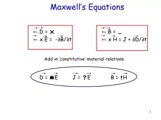
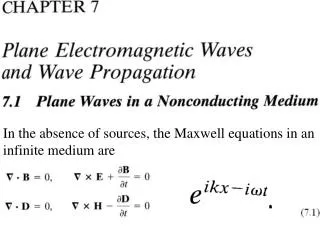
In the absence of sources, the Maxwell equations in an infinite medium are
For uniform isotropic linear media we have where and may in general be complex functions of ω. Assuming that they are real, positive and spatially constant. The equations for E and H are Assuming solutions with harmonic time dependence, the equations for the amplitude E(ω,x), etc. read
By combining the two equations we get the Helmholtz wave equation, real, positive and spatially constant Consider as a possible solution a plane wave traveling in x direction. From (7.3) we find the requirement that the wave number k and the frequency ω are related by The phase velocity of the wave is The quantity n is called the index of refraction and is usually a function of frequencyμ=μ(ω)
Using from (7.5), this can be written The primordial solution in one dimension is If the medium is non[dispersive μ(ω)], the Fourier superposition theorem (2.44) and (2.45) can be used to construct a general solution of the form A(k) μ(k) Where f(z) and g(z) are arbitrary functions.
If the medium is dispersive, equation (7.7) no longer holds. The wave changes shape as it propagates. We now consider an electromagnetic plane wave of frequency ω and wave vector and require that it satisfy not only the Helmholtz wave equation (7.3) but also all the Maxwell equations.With the convention that the physical electric and magnetic fields are obtained by taking the real parts of complex quantities, we write the plane wave fields as where and n are constant vectors.
Each component of E and B satisfies (7.3) provided To recover (7.4) it is necessary that n be a unit vector. With the wave equation satisfied, there only remains the fixing of the vectorial properties so that the Maxwell equations (7.1) are valid. The divergence equations in (7.1) demand that This means that E and B are both perpendicular to the direction of propagation n.
The factor can be written where n is the index of refraction defined in (7.5). The curl equations provide a further restriction, namely
where is an impedance.In vacuum, ohms, the impedance of free space. In engineering literature the magnetic field H is often displayed in parallel to E instead of B. The analog of (7.11) for H is
If n is real, (7.11) implies that and have the same phase. It is then useful to introduce a set of real mutually orthogonal unit vectors , as shown in Fig. 7.1.
In terms of these unit vectors the field strengths and are or The real part of the complex Poynting vector is: The energy flow (energy per unit area per unit time) is
The ratio of the magnitude of (7.13) to (7.14) shows that the speed of energy flow is as expected from (7.5). The time-averaged energy density u is correspondingly This gives, |S|=uv In the discussion that follows (7.11) we assumed that n \in R. This does not yield the most general possible solution for a plane wave.
Let n \in C, and write Then the exponential in (7.8) becomes, grows/decays in certain directions The relations (7.10) and (7.11) still hold. The requirement has real and imaginary parts, and implies that
The second of these conditions shows that andare orthogonal. The coordinate axes can be oriented so that is in the x direction and in the y direction. The first equation in (7.15) can be satisfied generally by writing, ch2x- sh2x=1,
The most general vector satisfying is then It is easily verified that for θ= 0, the solutions (7.12) and (7.12’) are recovered with Ch 0=1, sh 0=0.
The plane wave (7.8) and (7.12) is a wave with its electric field vector always in the direction . Evidently the wave described in (7.12’) is linearly polarized with polarization vector and is linearly independent of the first.
Thus the two waves, with can be combined to give the most general homogeneo-us plane wave propagating in the direction Note that the amplitudes E1 and E2 are complex numbers. If E1 and E2have the same (different) phases, (7.19) represents a linearly (elliptically) polarized wave.
If E1 and E2have the same (different) phases, (7.19) represents a linearly (elliptically) polarized wave. As shown in Fig. 7.2, its polarization vector making an angle with and a magnitude, if E1 and E2 are real.
Consider the case of circularly polarized wave where E1 and E2 have the same magnitude, but differ in phase by 90°. (E1, E2) = E0 (1,i). The wave (7.19) becomes: with E0 the common real amplitude.
The components of the actual electric field, obtained by taking the real part of (7.20), are (t upx down, y up) Ey=sin (ωt-kz) for + helicity
Ey=sin (ωt-kz) for + helicity At a fixed point space, the fields (7.21) are such that E is constant in magnitude, but sweeps around in a circle at frequency omega as shown in Fig. 7.3. circularly polarized, +(-) left(right)-polarized, counter-clockwise, positive(negative)helicity, for such a wave has a positive projection of L on the z-axis.
The two circularly polarized wave (7.20) form an equally acceptable set of basic fields for description of a general state of polarization. We introduce the complex orthogonal unit vectors: with properties, ε1, ε2 \in R, <a,b>=a*‧b
where E+ and E- are complex amplitudes. If E+ and E- have different magnitudes, but the same phase, (7.24) represents an elliptically polarized wave with principal axes of the ellipse in the directions of and . Then a general representation, equivalent to (7.19), is
If the amplitudes have a phase difference between them, then it is easy to show that the ellipse traced out by the E vector has its axes rotated by an angle (α/2), as shown in Fig.7.4.
The Stokes parameters can be motivated by observing that for a wave propagating in the z direction, the scalar products, are the amplitudes of radiation, respectively, with linear polarization in the x, y directions, +, - helicity. For the latter purpose we define each of the scalar coefficients in (7.19) and (7.24) as a magnitude times a phase factor: E1=? E2=?
In terms of the linear polarization basis , the Stokes parameters are If the circular polarization basis is used instead, the definitions read, same si as (7.27),
The parameter s0 measures relative intensity of the wave in either case.The parameter s1 gives the preponderance of x-linear polarization over y-linear polarization,s2 and s3 in the linear basis give phase information. RMK: The four Stokes parameters are not independent, since they depend on only three quantities. They satisfy the relation:
Monochromatic radiation, in practice, contains a range of frequencies and are not completely monochromatic. One way of viewing this is to say that the magnitudes and phases in (7.26) vary slowly in time, slowly, that is, when compared to the frequency ω. The observable Stokes parameters become averages over a relatively long time interval, and are written as T One consequence of the averaging process is that the Stokes parameters for a quasi-monochromatic beam satisfy an inequality,by Schwartz inequality, rather than the equality.Just Mention This Part!
The reflection and refraction of light at a plane surface between two media of different dielectric properties are familiar phenomena. The various aspects of this phenomena divide themselves into two classes. Kinematic properties:continuity of phase: k‧x|z=0 (a) Angle of reflection equals angle of incidence.(b) Snell’s law: (sin i)/(sin r) = n’/n 2. Dynamic properties:[from Maxwell equations](a) Intensities of reflected and refracted radiation.(b) Phase changes and polarization.
The coordinate system and symbols appropriate to the problem are shown in Fig. 7.5. The media below and above the plane z = 0 have permeabilities and permittivities and , respectively. C C
According to (7.18), the three waves are: Incident Refracted Reflected
Since , we find ; the angle of incidence equals the angle of reflection. Snell’s law is The wave number of the magnitudes The existence of boundary conditions at z = 0, which must be satisfied at all points on the plane at all times. We must have the phase factors all equal at z = 0, Independent of the nature of the boundary conditions. In the notation of Fig. 7.5,(7.34) reads,
The dynamic properties are contained in boundary conditions. In terms of fields (7.30)-(7.32) these boundary conditions at z = 0 are: First we consider the electric field perpendicular to the plane of incidence, as shown in Fig. 7.6a. The third and fourth equations in (7.37) give, E⊥ ,
E⊥ E//
For optical frequencies it is usually permitted to put . Using Snell’s law, the relative amplitudes of the refracted and reflected waves can be found from (7.38). For E perpendicular to plane of incidence, the Fresnel’s formula: E⊥
If the electric field is parallel to the plane of incidence, as shown in Fig. 7.6b., E// Using Snell’s law.For E parallel to plane of incidence:
Where the results on the right hold for . For normal incidence (i = 0), both (7.39) and (7.41) reduce to a -- sign for E⊥
For typical ratio . Two aspects of the dynamical relations on reflection and refraction are worthy of mention. The first is Brewster’s angle, and the second is total internal reflection. E// For polarization parallel to the plane of incidence there is an angle of incidence, called Brewster’s angle, for which there is no reflected wave. In (7.41), the amplitude of reflected wave vanishes when
Total internal reflection:Snell’s law (7.36) shows that, if n > n’, then r > i. Consequently, when where What happens if ? For , r is a complex angle with a purely imaginary cosine. Consider the propagation factor for the refracted wave. This shows that the wave is attenuated exponentially beyond the interface.
with , we find There is no energy flow through the surface. The lack of energy flow can be verified by calculating the time-averaged normal component of the Poynting vector just inside the surface: But n · k’=k’ cos r is purely imaginary, so that S · n =0.
E⊥ E// Total reflection:
Goos-Hächen effect: If a beam of radiation having a finite transverse extent undergoes total internal reflection, the reflected beam emerges displaced laterally with respect to the prediction of a geometrical ray reflected at the boundary. As shown in Fig. 7.7, the beam should emerge with a transverse displacement of The evanescent wave penetrating into the region z > 0 has an exponential decay in the perpendicular direction, where
Goos-Hächen effect: The first-order expressions for D for the two states of linear polarization are, kλ=2π, Where λ is the wavelength in the medium of higher index of refraction.