Download
1 / 25
250 likes | 403 Vues
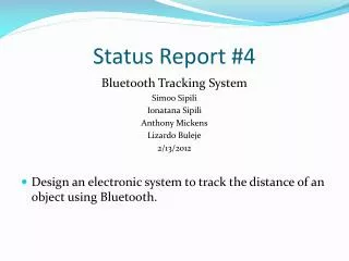
ATLAS/CMS/LCD RD53 collaboration: Pixel readout integrated circuits for extreme rate and radiation. LHCC status and outlook report June 4 2014 Jorgen Christiansen on behalf of RD53. Reminder RD53. Focussed R&D program to develop pixel chips for ATLAS/CMS phase 2 upgrades and LCD vertex

E N D
ATLAS/CMS/LCD RD53 collaboration: Pixel readout integrated circuits for extreme rate and radiation LHCC status and outlook report June 4 2014 Jorgen Christiansen on behalf of RD53
Reminder RD53 • Focussed R&D program to develop pixel chips for ATLAS/CMS phase 2 upgrades and LCD vertex • Extremely challenging requirements (ATLAS/CMS): • Small pixels: 50x50um2 (25x100um2) • Large chips: >2cm x 2cm ( ~1 billion transistors) • Hit rates: ~2 GHz/cm2 • Radiation: 1Grad, 1016neu/cm2 (unprecedented) • Trigger: 1MHz, 10us (~100x buffering and readout) • Low power - Low mass systems • Baseline technology: 65nm CMOS • Full scale demonstrator pixel chip in 3 year R&D program
Organisation issues • 19 Institutes (2 new institutes have joined) • Bari, Bergamo-Pavia, Bonn, CERN, CPPM, Fermilab, LBNL, LPNHE Paris, Milano, NIKHEF, New Mexico, Padova, Perugia, Pisa, Prague IP/FNSPE-CTU, PSI, RAL, Torino, UC Santa Cruz. • ~100 collaborators • 2 institutes requesting to join: LAL/OMEGA, Seville • Spokes persons: Maurice Garcia-Sciveres, LBNL (ATLAS), Jorgen Christiansen, CERN (CMS) • 2 year terms • Institute Board • IB chair: Lino Demaria, Torino • Regular IB meetings • MOU drafted and ready to be signed • Management board: Spokes persons, IB chair, WG conveners • Monthly meetings • Mailing lists, INDICO, CDS, TWIKI: http://twiki.cern.ch/RD53 , etc. set up • Technical Working Groups have started • WG conveners • Regular WG meetings • First official RD53 collaboration meeting (pre-RD53 meeting in Nov. 2012) • CERN April 10-11, 64 participants: https://indico.cern.ch/event/296570
Radiation WG • Radiation test and qualification of baseline 65nm technology for radiation levels of 1Grad and 1016neu/cm2 • WG convener: Marlon Barbero, CPPM • Activities and Status: • Defining radiation testing procedure • Test of 65nm transistors to 1Grad • NMOS: Acceptable degradation • PMOS: Severe radiation damage above 300Mrad (next slide) • Not yet a clear understanding of effects seen at these unprecedented radiation levels • ESD damage from manipulation and test systems ? • Systematic radiation/annealing studies required to be verified with pixel detector operation • Test of circuits to 1Grad • Ring oscillators, Pixel chips ( CERN, LBNL) • Some digital circuits remains operational up to 1Grad, depending on digital library used.(better than indicated by tests of individual transistors) Critical to confirm if 65nm is OK for inner layers of pixel detectors • Alternative foundries/technologies or replacement of inner layers after a few years ? • Plans • Systematic radiation and annealing studies of 65nm basic devices and circuits • Hadron/neutron radiation tests for NIEL effects • Radiation test of basic transistors/structures in alternative technologies (for comparison/understanding) • Simulation models of radiation degraded transistors (if possible) • CERN, CPPM, Fermilab, LBNL, New mexico, Padova
PMOS Radiation effects 65nm Transconductance Vt shift
PMOS Radiation effects 65nm Transconductance Vt shift
Radiation effects Birds beak parasitic device Spacer dielectrics may be radiation-sensitive Charge buildup in gate oxideand interface states affects Vt Thick Shallow Trench Isolation Oxide (~ 300 nm); radiation-induced charge-buildup may turn on lateral parasitic transistors and affect electric field in the channel) Doping profile along STI sidewall is critical; doping increases with CMOS scaling, decreases in I/O devices Increasing sidewall doping makes a device less sensitive to radiation (more difficult to form parasitic leakage paths)
Analog WG Krummenacher – TOT examples • Evaluation, design and test of appropriate low power analog pixel Front-Ends • Convener: Valerio Re, Bergamo/Pavia • Activities and status • Analogfront-end specifications • Planar, 3D sensors, capacitance, threshold, charge resolution, noise, deadtime, , • Alternative architectures –implementations to be compared, designed and tested by different groups • TOT, ADC, Synchronous, Asynchronous, Threshold adjust, Auto zeroing, etc. • Design / prototyping of FE’s ongoing • Plans • Prototyping and test (with radiation) different FEs • Some FEs have already been prototyped • Others will be prototyped after the summer • Test, comparison and choice of most appropriate FE(s) • Bergamo-Pavia, Bonn, CERN, CPPM, Fermilab, LBNL, Prague IP/FNSPE-CTU, Torino.
Top level WG • Global architecture and floor-plan issues for large mixed signal pixel chip • Convener: Maurice Garcia-Sciveres, LBNL • Activities and status • Global floorplan issues for pixel matrix • 50x50um2 – 25x100um2 pixels with same pixel chip • ATLAS – CMS has agreed to initially aim for this • Global floor-plan with analog and digital regions • Appropriate design flow • Column bus versus serial links • Simplified matrix structure for initial pixel array test chips • Plans • Submission of common simplified pixel matrix test chips • Evaluation of different pixel chip (digital) architectures • Using simulation frameworks from simulation WG. • Final integration of full pixel chip • Bonn, LBNL, , , ,
IP WG • Make IP blocks required to build pixel chips • Convener: Jorgen Christiansen, CERN • Activities and status • List of required IPs (30) defined and assigned to groups • Review of IP specs June 2014 • Defining how to make IPs appropriate for integration into mixed signal design flow for full/final pixel chips • IP expert panel • CERN design flow • Design of IP blocks have started • Plans • Common IP/design repository • Prototyping/test of IP blocks 2014/2015 • IP blocks ready 2015/2016 • ~All RD53 institutes
Simulation/verification WG • Simulation and verification framework for complex pixel chips • Convener: Tomasz Hemperek, Bonn • Activities and status • Simulation framework based on system Verilog and UVM (industry standard for ASIC design and verification) • High abstraction level down to detailed gate/transistor level • Benchmarked using FEI4 design • First basic version of framework available on common repository • Internal generation of appropriate hit patterns • Used for initial study of buffering architectures in pixel array • Integration with ROOT to import hits from detector simulations and for monitoring and analysing results. • Plans • Refine/finalize framework with detailed reference model of pixel chip • Import pixel hit patterns from detector Monte-Carlo simulation • Modelling of different pixel chip architectures and optimization • Verification of final pixel chip • Bonn, CERN, Perugia Buffer occupancy comparison between simulation and analytical statistical model
RD53 Outlook • 2014: • Release of CERN 65nm design kit. RD53 eagerly awaiting NDA issues to be resolved. • Detailed understanding of radiation effects in 65nm • Radiation test of few alternative technologies. • Spice models of transistors after radiation/annealing • IP/FE block responsibilities defined and appearance of first FE and IP designs/prototypes • Simulation framework with realistic hit generation and auto-verification. • Alternative architectures defined and efforts to simulate and compare these defined • Common MPW submission 1: First versions of IP blocks and analogFEs • 2015: • Common MPW submission 2: Near final versions of IP blocks and FEs. • Final versions of IP blocks and FEs: Tested prototypes, documentation, simulation, etc. • IO interface of pixel chip defined in detail • Global architecture defined and extensively simulated • Common MPW submission 3: Final IPs and FEs, Initial pixel array(s) • 2016: • Common engineering run: Full sized pixel array chip. • Pixel chip tests, radiation tests, beam tests , , • 2017: • Separate or common ATLAS – CMS final pixel chip submissions.
Summary • RD53 has gotten a good start • Organization structure put in place • Technical work in WGs have started The development of such challenging pixel chips across a large community requires a significant organisation effort. • Radiation tolerance of 65nm remains critical • Design work has started in 65nm (FEs, IPs) • Annealing effects/scenario to be understood • Backup: Inner layer replacement versus alternative technology • RD53 is now a recognized collaboration requested to report in relevant HEP/pixel meetings, conferences and workshops: • ATLAS/CMS meetings • ACES2014: https://aces.web.cern.ch/aces/aces2014/ACES2014.htm • Front-end electronics workshop: http://indico.cern.ch/event/276611/overview • Pixel/Vertex • Funding for RD53 work starts to materialize in institutes • CMS and ATLAS rely fully on RD53 for their pixel upgrades
IO WG • Defining and implementing readout and control interfaces • Convener: To be assigned • Not (yet) urgent • Plans • Defining readout and control protocols • Implement/verify IO blocks for pixel chip • Standardized pixel test systems
Phase 2 pixel challenges • ATLAS and CMS phase 2 pixel upgrades very challenging • Very high particle rates: 500MHz/cm2 • Hit rates: 1-2 GHz/cm2 (factor 16 higher than current pixel detectors) • Smaller pixels: ¼ - ½ (25 – 50 um x 100um) • Increased resolution • Improved two track separation (jets) • Participation in first/second level trigger ? • 40MHz extracted clusters (outer layers) ? • Region of interest readout for second level trigger ? • Increased readout rates: 100kHz -> 1MHz • Low mass -> Low power Very similar requirements (and uncertainties) for ATLAS & CMS • Unprecedented hostile radiation: 1Grad, 1016Neu/cm2 • Hybrid pixel detector with separate readout chip and sensor. • Phase2 pixel will get in 1 year what we now get in 10 years • Pixel sensor(s) not yet determined • Planar, 3D, Diamond, HV CMOS, , , • Possibility of using different sensors in different layers • Final sensor decision may come relatively late. • Very complex, high rate and radiation hard pixel readout chips required ATLAS HVCMOS program
Pixel upgrades • Current LHC pixel detectors have clearly demonstrated the feasibility and power of pixel detectors for tracking in high rate environments • Phase1 upgrades: Additional pixel layer, ~4 x hit rates • ATLAS: Addition of inner B layer with new 130nm pixel ASIC (FEI4) • CMS: New pixel detector with modified 250nm pixel ASIC (PSI46DIG) • Phase2 upgrades: ~16 x hit rates, 2-4 x better resolution, 10 x readout rates, 16 x radiation tolerance, Increased forward coverage, less material, , , • Installation: ~ 2022 • Relies fully on significantly improved performance from next generation pixel chips. CMS & ATLAS phase 2 pixel upgrades ATLAS Pixel IBL CMS Pixel phase1 100MHz/cm2 400MHz/cm2 1-2GHz/cm2
Pixel chip • Pixel readout chips critical for schedule to be ready for phase 2 upgrades • Technology: Radiation qualification • Building blocks: Design, prototyping and test • Architecture definition/optimization/verification • Chip prototyping, iterations, test, qualification and production • System integration • System integration tests and test-beams • Production and final system integration, test and commissioning • Phase 2 pixel chip very challenging • Radiation • Reliability: Several storage nodes will have SEUs every second per chip. • High rates • Mixed signal with very tight integration of analog and digital • Complex: ~256k channel DAQ system on a single chip • Large chip: ~2cm x 2cm, ½ - 1 Billion transistors. • Very low power: Low power design and on chip power conversion • Both experiments have evolved to have similar pixel chip architectures and plans to use same technology for its implementation. • Experienced chip designers for complex ICs in modern technologies that most work in a extremely harsh radiation environment is a scarce and distributed “resource” in HEP.
3rd generation pixel architecture • 95% digital (as FEI4) • Charge digitization • ~256k pixel channels per chip • Pixel regions with buffering • Data compression in End Of Column
Why 65nm Technology • Mature technology: • Available since ~2007 • High density and low power • Long term availability • Strong technology node used extensively for industrial/automotive • Access • CERN frame-contract with TSMC and IMEC • Design tool set • Shared MPW runs • Libraries • Design exchange within HEP community • Affordable (MPW from foundry and Europractice, ~1M NREfor full final chips) • Significantly increased density, speed, , ,and complexity ! X. Llopart CERN G. Deptuch, Fermilab
65nm Technology • Radiation hardness • Uses thin gate oxide • Radiation induced trapped charges removed by tunneling • More modern technologies use thick High K gate “oxide” with reduced tunneling/leakage. • Verified for up to 200Mrad • To be confirmed for 1Grad • PMOS transistor drive degradation, Annealing ? • If significant degradation then other technologies must be evaluated and/or a replacement strategy must be used for inner pixel layers • CMOS normally not affect by NIEL • To be confirmed for 1016Neu/cm2 • Certain circuits using “parasitic” bipolars to be redesigned ? • SEU tolerance to be build in (as in 130 and 250nm) • SEU cross-section reduced with size of storage element, but we will put a lot more per chip • All circuits must be designed for radiation environment ( e.g. Modified RAM) S. Bonacini, P. Valerio CERN No radiation after annealing 950Mrad M. Menouni, CPPM
ATLAS – CMS RD collaboration • Similar/identical requirements, same technology choice and limited availability of rad hard IC design experts in HEP makes this ideal for a close CMS – ATLAS RD collaboration • Even if we do not make a common pixel chip • Initial 2day workshop between communities confirmed this. • Workshop: http://indico.cern.ch/conferenceDisplay.py?confId=208595 • Forming a RD collaboration has attracted additional groups and collaborators • Synergy with CLIC pixel (and others): Technology, Rad tol, Tools, etc. • Institutes: 17 • ATLAS: CERN, Bonn, CPPM, LBNL, LPNHE Paris, NIKHEF, New Mexico, RAL, UC Santa Cruz. • CMS: Bari, Bergamo-Pavia, CERN, Fermilab, Padova, Perugia, Pisa, PSI, RAL, Torino. • Collaborators: 99, ~50% chip designers • Collaboration organized by Institute Board (IB) with technical work done in specialized Working Groups (WG) • Initial work program covers ~3 years to make foundation for final pixel chips • Will be extended if appropriate: • Common design ?, • Support to experiment specific designs
? Ring oscillators with different transistor sizes at -25oC