Project 251
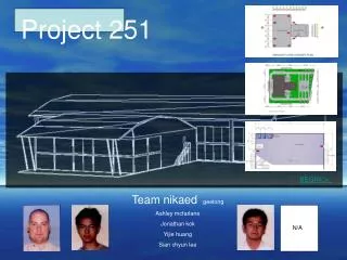
Project 251. BEGIN/:>_. Team nikaed geelong Ashley mcfarlane Jonathan kok Yijie huang Sian chyun lee. N/A. Project 251. Proposed site building permits sites visits architectural design final design. SITE PLAN. FLOOR PLAN. STRUCTURAL. PARKING/OFF-SET RETAINING WALL. General layout

Project 251
E N D
Presentation Transcript
Project 251 BEGIN/:>_ Team nikaed geelong Ashley mcfarlane Jonathan kok Yijie huang Sian chyun lee N/A
Project 251 Proposed sitebuilding permitssites visitsarchitectural designfinal design SITE PLAN FLOOR PLAN STRUCTURAL • PARKING/OFF-SET • RETAINING WALL • General layout • Services/exits • Fire-rating door • Pallets layout • Warehouse and showroom • Mezzanine flooring system PREVIOUS PAGE NEXT PAGE
Proposed site TEAM TO UNDERTAKE THE DESIGN AND DOCUMENTATION OF A WAREHOUSE AND OFFICE COMPLEX OFF GRUNGE ROAD, GEELONG VICTORIA. REVIEW OF STRUCTURAL SYSTEMS APPROPRIATE FOR WAREHOUSE AND OFFICE SPACES. RECOMMENDATION OF APPROPRIATE STRUCTURE SYSTEM FOR THE PROJECT. REVIEW OF ENVELOPE SYSTEMS APPROPRIATE FOR BOTH WAREHOUSE AND OFFICE SPACES. RECOMMENDATION OF APPROPRIATE ENVELOPE SYSTEMS FOR THE PROJECT INDICATIVE STRUCTURAL SECTIONS AND SIZES FOR ELEMENTS OF WAREHOUSE AND OFFICE BUILDINGS. INFORMATION ON SPAN, SPACING, MEMBER SIZE AND LOADING ON STRUCTURE SCHEMATIC DESIGN LAYOUT OF BUILDING PROPOSAL, BUILDING PLANNING, PLANS AND SECTION TEAM TO UNDERTAKE THE DESIGN AND DOCUMENTATION OF A WAREHOUSE AND OFF ICE COMPLEX OFF GRUNGE ROAD, GEELONG VICTORIA.REVIEW OF STRUCTURAL SYSTE MS APPROPRIATW FOR WAREHOUSE AND OFFICE SPACES.RECOMMENDATION OF APPR OPRIATE STRUCTURAL FOR THE PROJECT.REVIEW OF ENVELOPE SYSTEMS APPROPRIA TE FOR BOTH WAREHOUSE AND OFFICES SPACES.RECOMMENDATION OF APPROPRIAT E ENVELOPE SYSTEMS FOR THE PROJECTINDICATIVE STRUCTURAL SECTIONS AND SIZ ES FOR ELEMENTS OF WAREHOUSE AND OFFICE BUILDINGS.INFORMATION ON SPAN, SPACING, MEMBER SZIE AND LOADING ON STRUCTURESCHEMATIC DESIGN LAYOUT OF BUILDING PROPOSAL, BUUILDING PLANNING, PLANS AND SECTION TEAM TO UNDERTA KE THE DESIGN AND DOCUMENTATION OF A WAREHOUSE AND OFF ICE COMPLEX OFF GRUNGE ROAD, GEELONG VICTORIA.REVIEW OF STRUCTURAL SYSTE MS APPROPRIATW FOR WAREHOUSE AND OFFICE SPACES.RECOMMENDATION OF APPR OPRIATE STRUCT URAL FOR THE PROJECT.REVIEW OF ENVELOPE SYSTEMS APPROPRIA TE FOR BOTH WA REHOUSE AND OFFICES SPACES.RECOMMENDATION OF APPROPRIAT E ENVELOPE SYS TEMS FOR THE PROJECTINDICATIVE STRUCTURAL SECTIONS AND SIZ ES FOR ELEMEN TS OF WAREHOUSE AND OFFICE BUILDINGS.INFORMATION ON SPAN, SPACING, MEMBE R SIZE AND LOADING ON STRUCTURESCHEMATIC DESIGN LAYOUT OF BUILDING PROP OSAL, BUUILDING PLANNING, PLANS AND SECTION TEAM TO UNDERTAKE THE DESIGN AND DOCUMENTATION OF A WAREHOUSE AND OFF ICE COMPLEX OFF GRUNGE ROAD, GEELONG VICTORIA.REVIEW OF STRUCTURAL SYSTE MS APPROPRIATW FOR WAREHOU SE AND OFFICE SPACES.RECOMMENDATION OF APPR OPRIATE STRUCTURAL FOR THE PROJECT.REVIEW OF ENVELOPE SYSTEMS APPROPRIA TE FOR BOTH WAREHOUSE AND OFFICES SPACES.RECOMMENDATION OF APPROPRIAT E ENVELOPE SYSTEMS FOR THE MAIN PAGE PREVIOUS PAGE NEXT PAGE
Building permits MAIN PAGE PREVIOUS PAGE NEXT PAGE
Sites visits MAIN PAGE PREVIOUS PAGE NEXT PAGE
Phase 1 Architectural design MAIN PAGE PREVIOUS PAGE NEXT PAGE
Phase 2 Architectural design MAIN PAGE ARCHITECTURAL DESIGN PAGE PREVIOUS PAGE NEXT PAGE
Architectural design Final design Phase 3 plan Front elevation end elevation MAIN PAGE ARCHITECTURAL DESIGN PAGE PREVIOUS PAGE NEXT PAGE
Site plan • CLICK HERE • PARKING/OFF-SET • RETAINING WALL MAIN PAGE PREVIOUS PAGE NEXT PAGE
PARKING/OFF-SET The design requirements for the car parking spaces was determined from the information required from the planning code of victoria. The planning documents were supplied by chakir design and planning. We have used the minimum car dimensions of 2.6M X 4.9M. MAIN PAGE SITE PLAN PAGE PREVIOUS PAGE NEXT PAGE
PARKING/OFF-SET MAIN PAGE SITE PLAN PAGE PREVIOUS PAGE NEXT PAGE
PARKING/OFF-SET MAIN PAGE SITE PLAN PAGE PREVIOUS PAGE NEXT PAGE
MAIN PAGE SITE PLAN PAGE RETAINING WALL • The retaining wall is used around the perimeters of the site. This system is to be a pre-cast concrete panel wall, with screenings and a bitumen DPC’s. We have also chosen an agricultural pipe and electric pump for drainage purposes. Refer to detail. (courtesy of Fallaw & associates engineers) PREVIOUS PAGE NEXT PAGE
Floor plan • CLICK HERE: • General layout • Services/exits • Fire-rating door • Pallets layout Our floor plan is based on a grid system to indicate the location of the external columns. We have used spacings of 9000 by 6000 maximum centers to columns. MAIN PAGE PREVIOUS PAGE NEXT PAGE
General layout Consideration was made on determining the pallet and storage layout. This was the first design strategy taken into account. The colored bars shown on plan indicates the minimum requirement for access and storage. Driving lane Pallet MAIN PAGE FLOOR PLAN PAGE PREVIOUS PAGE NEXT PAGE
Services/exits The exits allocated conforms to the building code of Australia under the section; provisions of escape. According to the building code, the warehouse is classified as a class 7(b) and needs a path of travel, not further than 20m to the nearest exit. To conform to the code, we allocated 4 exits in the warehouse of a width of 2m The showroom and mezzanine, which is a building of class 5, has 2 exits on each level allocated of 1m in width. MAIN PAGE FLOOR PLAN PAGE PREVIOUS PAGE NEXT PAGE
MAIN PAGE FLOOR PLAN PAGE Services/exits PREVIOUS PAGE NEXT PAGE
MAIN PAGE FLOOR PLAN PAGE Fire-rating door Refer to AS 1905.1: 1997 PREVIOUS PAGE NEXT PAGE
MAIN PAGE FLOOR PLAN PAGE Fire-rating door PREVIOUS PAGE NEXT PAGE
MAIN PAGE FLOOR PLAN PAGE Pallet layout • Factors in determing style and size of pallet • Size of the carrier in shipping and receiving • Size and weight of items • Dimension of floor space • Type of equipment used (forklift) • Slave pallet versus nonslave pallets consideration • Cost, supply and maintenance • Aisle widths, door sizes and height clearances Pallets sizes- -24 x 32 in. 42 x 42 in. -32 x 40 in. 48 x 40 in. -32 x 48 in. 48 x 48 in. -36 x 36 in. 48 x 60 in. -36 x 42 in. 48 x 72 in. -40 x 48 in. PREVIOUS PAGE NEXT PAGE
Pallet layout The pallet layout of warehouse depends on the physical structure and location of the receiving and shipping departments. There is no single fixed path over which all parts and materials are moved. It is not possible to define a single material flow pattern that would be ideal for a storage facilities. Lifting equipment for example an forklift play an important part in material moves that define the flow pattern. Optimum Floor planning by destining departments with the most frequent interchange of parts to be placed next to one another. Proposed pallet layout -3.6 meter minimum driving space for forklift -2 access lanes MAIN PAGE FLOOR PLAN PAGE PREVIOUS PAGE NEXT PAGE
structural Click on image to play/halt the animation. PREVIOUS PAGE NEXT PAGE
structural Roof truss and rafter systems wall systems Mezzanine floor Footings and retaining wall Please Click on Headings to Link: MAIN PAGE PREVIOUS PAGE NEXT PAGE
Warehouse and showroom Roof truss and rafter systems There are two systems which we investigated. The first system was based on a curved rafter portal frame. We found the standard portal frame rafters were a cheaper and less labor intensive. However a more expensive truss system was chosen for aesthetic reasons. The factors that determine the cost of producing these trusses is based on the cost of specialist labor needed to pre-fabricate the trusses off-site. Welding is common in this form of pre-fabricated system therefore production cost is much more expensive. MAIN PAGE STRUCTURAL PAGE PREVIOUS PAGE NEXT PAGE
MAIN PAGE STRUCTURAL PAGE Roof structure system • THERE ARE THREE TYPES OF CLADDING WHICH WE HAVE CHOSEN FOR THIS PROJECT. • LBI KLIP-LOK WILL BE USED FOR THE ROOF SHEETING. IT IS READILY AVAILABLE AND SUITABLE FOR WAREHOUSE APPLICATIONS. KLIP-LOK DECKS ARE AVAILABLE FACTORY CUTS TO LENGHTS OF 10MM INCREMENTS UP TO 15000MM INCREMENTS. • LBI CUSTOM ORB WAS CHOSEN FOR THE WALL CLADDING WHICH IS SITUATED AT THE SIDES OF THE TRUSSES. THIS SYSTEM IS A CORRIGATED ZINC/ALUMINIUM ALLOY-COATED STEEL SHEET AND COMES IN MANY COLOURS. THE CONECTIONS USED FOR THE CUSTOM ORB CLADDING CAN BE BOUGHT OFF THE SHELF FROM LOCAL HARDWARE STORES. AVAILABLE IN STOCK LENGHTS UP TO 9000MM OR FACTORY CUT TO LENGHTS IN 10MM INCREMENTS. LONGER LENGHTS CAN BE SUPPLIED. • LBI PANEL RIB CLADDING WAS USED FOR THE REST OF THE PORTAL FRAMED WALLS, AND PROVIDES A DIFFERENT PROFILE TO THE CUSTOM ORB SHEETING. PANELRIB IS AVAILABLE IN STOCK LENGHTS FROM 1200 TO 5000MM OR CUSTOM CUT TO LENGHTS UP TO 6500MM, LONGER LENGHTS SUBJECT TO ENQUIRY. PREVIOUS PAGE NEXT PAGE
MAIN PAGE STRUCTURAL PAGE Roof structure system • TWO TYPES OF GUTTERING SYSTEMS CAN BE USED FOR THIS PROJECT • SHEER LINE & TRIM LINE GUTTER PROFILES ARE SUITABLE FOR ALL TYPES OF ROOFS. • AS A GUIDE TABLE A GIVES EXAMPLES OF MAXIMUM LENGTH SHEET RUNS FOR VARIOUS LBI SHEET RPOFILES. THE SHEET RUN IS THE TOTAL LENGTH OF ROOF SHEETING OR EXPANSION JOINTS THAT MAY BE INCLUDED IN THE ROOF STRUCTURE. • AS A GUIDE TABLE B CALCULATES RAINFALL INTENSITIES FOR SELECTED LOCATIONS. REFER TO VICTORIA IN TABLE B PREVIOUS PAGE NEXT PAGE
MAIN PAGE STRUCTURAL PAGE Roof structure system PREVIOUS PAGE NEXT PAGE
MAIN PAGE STRUCTURAL PAGE Roof structure system PREVIOUS PAGE NEXT PAGE
Roof structure system Refer to: Lysaght Purlins & Girts User’s Manual: NSW MAIN PAGE STRUCTURAL PAGE PREVIOUS PAGE NEXT PAGE
Roof structure system • Economical alternative to timber roof battens. • Storage, carrying and handling are eaiser as they nest together. • Quicker and easier to install • Eliminating the time-consuming process of cutting to length. • Consistent straightness aid alignment and fastening is quick and easy. MAIN PAGE STRUCTURAL PAGE PREVIOUS PAGE NEXT PAGE
wall structure system WE HAVE CHOSEN PRE-CAST CONCRETE PANELS TO BE ERRECTED BETWEEN THE SHOWROOM AND WAREHOUSE AREAS. THE PANELLING WIDTH WILL BE 200mm AND WAS CHOSEN TO PROVIDE ADEQUATE FIRE RATING. THIS PRODUCT CAN BE RENDERED OR POLISHED. CONCRETE WALLS CAN BE CUSTOMIZED WITH DESIRED AESTHETIC PATTERNS ADDED TO THE CONCRETE PANEL BEFORE CURING.THIS PRODUCT CAN BE CAST ON-SITE WHICH SAVESON TRANSPORTATION, COSTS, AND LABOR. HOWEVER THE FINISHED SURFACE MAY NOT BE AS COMPARABLE TO PRE-CAST OFF-SITE. MAIN PAGE STRUCTURAL PAGE PREVIOUS PAGE NEXT PAGE
wall structure system bracing BRACING WILL BE USED ON THE LAST BAY OF THE WALL AND ROOF. CROSS BRACING IS USED TO HOLD THE RAFTER AND COLUMNS TOGETHER TO SUPPORT THE STRUCTURE AGAINST WIND LOADS. Refer to AS 4055 and AS 4055amd1 MAIN PAGE STRUCTURAL PAGE PREVIOUS PAGE NEXT PAGE
wall structure system bracing EXAMPLES OF BRACING CONNECTIONS MAIN PAGE STRUCTURAL PAGE PREVIOUS PAGE NEXT PAGE
Showroom/offices The show room is designed for universal displacement. It has a totally opening entrance with large shade less window which could provide sufficient sunlight. The backwards of the show room provides a lunch area and universal access toilets For office workers and front desk sales. With a 2.8m width fire rating doors, It connected the showroom to the ware house. MAIN PAGE STRUCTURAL PAGE PREVIOUS PAGE NEXT PAGE
footing system • The proposed site soil classification is CLASS M • pad footing to be used under all load bearing wall and column. Refer to: AS 2870 AS 2870s1 AS 2870amd1 AS 2870amd2 AS 2870amd3 AS 2870amd4 SECTION OF TYPICAL PAD FOOTING DETAIL MAIN PAGE STRUCTURAL PAGE PREVIOUS PAGE NEXT PAGE
Mezzanine flooring system THE MEZZANINE FLOOR PROVIDES OFFICE SPACE WHIICH CAN BE ARRANGED TO ITS DESIRED CONFIGURATION. BASIC AMENITIES AND SANITARY SPACES HAD BEEN ALLOCATED BASED ON THE STANDARDS OF THE BUILDING CODE, IN THE ASPECTS OF PROVISIONS FOR ESCAPE, AND STANDARD BUILDING CLASS REQUIREMENTS. THE ISSUE OF UNIVERSAL ACCESS HAD ALSO BEEN ADRESSED WITH THE FITTING OF HANDICAP TOILETS, AND AN ELEVATOR SERVICE. FOR SAFETY REQUIREMENTS, TWO EXTERNAL STAIRS IS PROVIDED LEADING TO THE GROUND LEVEL. PREVIOUS PAGE MAIN PAGE STRUCTURAL PAGE NEXT PAGE
STRUCTURALLY, THE MEZZANINE COMPRISSES COLUMNS WHICH ARE LOCATED BASED ON GRID SYSTEM WHICH DETERMINES THE ENTIRE STRUCTURE’S COLUMN PLACEMENT. 30mm THICK STRUCTAFLOR PLYWOOD STRIPFLOORING HAD BEEN CHOSEN TO BE THE MAIN FLOOR CLADDING, WITH FLOOR JOISTS SPACING OF 450mm. THE BEARERS, WHICH SPANS 5400mm HAD BEEN LOCATED TO ACHIEVE THE MAXIMUM ALLOWABLE SPAN DISTANCE. MAIN PAGE STRUCTURAL PAGE PREVIOUS PAGE NEXT PAGE
CLICK ON CHART TO ACCESS PDF FILE SELECTION OF THE MEMBERS WAS BASED ON THESE TABLES ABOVE WITH THE CONSIDERATION OF MAINTAINING THE BALANCE OF PRESENTABLE SIZES IN TERMS OF AESTHETICS, AND ACHIEVING MAXIMUM SPAN DISTANCE IN THE STRUCTURE. MAIN PAGE STRUCTURAL PAGE PREVIOUS PAGE NEXT PAGE
Credits AISC, Australian Institute of Steel Construction Handout Bluescope Lysaght http://www.lysaght.com CCH Australia Limited. Australia Building Codes Board (1996). Building Code of Australia 1996 – Volume One and Two http://www.abcb.gov.au Chakir Design and Planning Email: cdoffice@bigpond.net.au City of Greater Geelong City Council http://www.geelongaustralia.com.au DuraGal Mezzanine Flooring System D. R. Sule (1988). Manufacturing Facilities, Location, Planning and Design. USA: PWS-KENT Publishing Company FIRE PROTECTION ASSOCATION AUSTRALIA http://www.fpaa.com.au/Passive/passive.html James A Tompkins and John A. White (1984). Facilities Planning. USA: John Wiley & Sons, Inc. MINESCO PTY LTD 14 -18 Reid St Ardeer 3022, (03) 8361 8150 John Lysaght (1985). Lysaght Referee (27TH ED). Wollongong, NSW: Mercury Tradeset. The Planning Code of Australia Particular Provisions – Clause 52.06 MAIN PAGE