OPTICAL FIBRE COMMUNICATION
OPTICAL FIBRE COMMUNICATION. 2011 AUGUST. Pcm equipment. Pcm equipment(2) contd. Global Capacity Trend. Source: www.internetworldstats.com. Europe 810 Million. North America 335 Million. 6Tbps. Asia 3.7 Billion. 12Tbps. Middle East 193 Million. 6Tbps. 2-3Gbps. 9Tbps. 5Tbps.


OPTICAL FIBRE COMMUNICATION
E N D
Presentation Transcript
OPTICAL FIBRE COMMUNICATION 2011 AUGUST
Global Capacity Trend Source: www.internetworldstats.com
Europe 810 Million North America 335 Million 6Tbps Asia 3.7 Billion 12Tbps Middle East 193 Million 6Tbps 2-3Gbps 9Tbps 5Tbps 8Tbs Africa 933 Million Latin America/ Caribbean 557 Million Oceania/ Australia 34 Million Current Estimated Capacities between Continents
LIGHT Light is an is electromagnetic radiation of a wavelength that is visible to the human eye
CHARACTERISTICS OF LIGHT • Light is made up of , either electromagnetic wave or particles called photons. Light can be considered as rays that follows straight line between or within optical elements, bending only at surfaces.
Light is composed of electrical & magnetic fields, which vary in amplitude as they move through space together at the speed of the light. The two fields are perpendicular to each other and to the direction on which the light travels.
MEDIUM Medium is a material substance which can transmit energy waves. E.g. Air, Liquid, Solid Air Liquid Solid
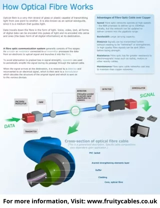
Transmitter Receiver ELECTRICITY LIGHT ELECTRICITY Avalanche Photo Diode Glass Fibre LED/Laser Light Source Light Source What is Optical Fibre? • Basic Theory : • Light has to be confined to the core so that the digital signal can be transmitted from one place to another through light. An optical fibre consists 3 different parts. Core Cladding Buffer Coating • Basic Elements of the Optical Fibre System :
Refractive Index Light changes its speed when it travels from one material to another, such as from air into glass. This cause an effect called refraction. Hence bending of the light at the surface of a material is expected. The speed of the light in the vacuum is highest. Medium 1 n1 Ө1 Sin Ө1 n 2 Sin Ө2 n 1 Medium 2 n2 Ө2 Sin Ө1 n 2 Sin Ө2 n 1 n1 SinӨ1 = n2 SinӨ2 Basic Theorems behind Optical Fibre (a) • Snell’s Law • Snell's lawstates that the ratio of the sines (Sin) of the angles of incidence and refraction is equivalent to the ratio of velocities in the two media, or equivalent to the opposite ratio of the indices of refraction. n1< n2
When the refraction angle reaches90°, there is no refraction and the incident anglereaches its critical angle (ΦC) When incident angle reaches the critical angle, there is no refraction. Beyond the critical angle, light ray becomes totally internally reflected . Critical Angle & Total Internal Reflection Basic Theorems behind Optical Fibre (b) • According to the increase of the angle of incidence, the angle of refraction increases. Medium 2 n2 Φ2 Φ1 ΦC Medium 1 n1 Total Internal Reflection
Special points to be considered in optical fibre (a) • Numerical Aperture (NA) • NA is defined as the sine of half the angle of a fibre’s light acceptance cone (see Figure). • All modes of light entering the fiber at angles less than that which correspond to the NA, will be bound or confined to the core of the fiber. • The larger the NA of a fiber, the larger the light acceptance cone.
Numerical Aperture consideration From Snell’s Law : Cladding n2 90 - ΦC ΦC Air n0 = 1 Core n1 αmax n0Sinαmax = n1Sin(90 - ΦC) n1Sin ΦC = n2Sin90
Numerical Aperture Calculation n0Sinαmax = n1Sin(90 - ΦC) n1Sin ΦC = n2Sin90
What is Acceptance Angle? Fibre accepting angle: Therefore, nosinαmax = NA NA determines the light gathering capabilities of the fibre
Question 1 A silica optical fibre with a core diameter large enough to be considered by ray theory analysis has a core refractive index of 1.50 and a cladding refractive index of 1.47 Determine: (a) the critical angle at the core cladding interface; (b) the NA for the fibre; (c) the acceptance angle in air for the fibre
Solution: • The critical angle at the core-cladding interface (b) The numerical aperture is: (c) The acceptance angle in air θa is:
E.g. The speed of light in water V(l) is 2.24 x 10 8 ms -1 and the speed of light in a vacuum V(V) is 2.99 x 10 8 ms -1. What is the Refractive index of Water(n w)? V(l) = 2.24 x 10 8 ms -1 V(V) = 2.99 x 10 8 ms -1 Refractive index of water = V(V) V(l) = 2.99 x 10 8 ms -1 2.24 x 10 8 ms -1 = 1.33 So The Refractive Index of water is 1.33 (No units).
What is Snell’s Law? • This describes the bending of light rays when it travels from one medium to another. Air Glass Water Air
Snell's law states that the ratio of the sines (Sin) of the angles of incidence and refraction is equivalent to the ratio of velocities in the two media, or equivalent to the opposite ratio of the indices of refraction. Sin Ө1 n 2 = Sin Ө2 n 1 Sin Ө1 n 2 = Sin Ө2 n 1 n 1 Sin Ө1 = n 2 Sin Ө 2 PO - Ray of Incidence n 1 - RI for medium 1 OQ - Ray of Refraction n 2 - RI for medium 2 Ө 1 - Angle of Incidence Ө 2 - Angle of Refraction
TOTAL INTERNAL REFLECTION n 1 Sin Ө1 = n 2 Sin Ө 2 With the increase of the angle of incidence, the angle of refraction increases accordingly. When reaches φ290°, there is no refraction and φ1reaches a critical angle (φc) Beyond the critical angle, light ray becomes totally internally reflected
EQUATIONS ASSOCIATED WITH RAY PROPAGATION • CRITICAL ANGLE • NUMERICAL APERTURE
LIGHT GATHERING CAPACITY • An optical fibre will pick up light from any source. However collecting light for small core fibres will be a important step towards communication fibres. This means collecting light from one source and transferring that light to the optical fibre. This demands COUPLING light from core to the fibre, in a efficient way. Larger light sources are generally easy to align with fibres, but their lower intensity generally delivers less light. Transferring light between fibres requires careful alignment and tight tolerance. When two fibres’ are permanently joined are called SPLICING. Temporary joints made by two fibres are called as CONNECTORS. Special device named COUPLERS are needed to join 3 or more fibres. Losses in transferring signals in copper can be neglected but it is not so with fibres. Hence it should account for the losses deriving from coupling , from connectors, splices and the efficiency of the light source into the fibre.
NUMERICAL APPERATURE • LIGHT GATHERING CAPACITY OF A OPTICAL FIBRE CABLE IS DEFINED AS THE NUMERICAL APPERTURE • THE ACCEPTANCE ANGLE IS THE ANGLE WHERE THE OF SOURCE ISINTRODUCED TO THE FIBRE
Optical Fibre • An optical fibre consists of two parts the core and the cladding • The core is a narrow cylindrical strand of glass and the cladding is a tubular jacket surrounding it • The core has a (slightly) higher refractive index than the cladding Therefore, total Reflection of light ncore > ncladding
Question 1: A silica optical fibre with a core diameter large enough to be considered by ray theory analysis has a core refractive index of 1.50 and a cladding refractive index of 1.47 • Determine: • The critical angle at the core cladding interface; • The NA for the fibre • The acceptance angle in air for the fibre
This means the angle over which the light rays entering the fibre , to be guided along it’s core. Acceptance angle is measured in air outside the fibre ,it defers from confinement angle of the
MODES OF FIBRE • There are 2 main type of modes in optical Fibre • SINGLE MODE • STEP INDEX • MULTIMODE • STEP INDEX • GRADED INDEX
Optical Fibre Transmission System Major components • Modulator • Light source • Connectors (Couplers) • Optical glass Fibre • Light sensor/Detector • Optical amplifiers/Repeaters • Optical fibre joints (splices)