Download

1 / 40
460 likes | 684 Vues
PLC Applications [ATE-1212] Module-1. Control task planning and implementation. Module Objectives. 1. Analyze a control task by defining its Inputs and Outputs , and its technical requirements.

E N D
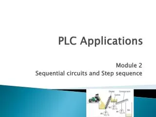
PLC Applications[ATE-1212]Module-1 Control task planning and implementation
Module Objectives 1. Analyze a control task by defining its Inputs and Outputs, and its technical requirements. 2.Configure control task hardware by selecting the proper LOGO! Basic module and its expansion modules. 3.Develop control routines and design an Industrial Process control program from beginning to end using LOGO Soft Comfort software. 4.Use normally open and normally close sinking and sourcing sensors 5.Understand and apply interlocks, and latches
Introduction • Small control tasks can be solved using LOGO! with a minimum of hardware. • As you studied in PLC course input signals supply LOGO! with information on the currentstate of the process and any operator commands. • The control relays react to these input signals in accordance with a defined program. • It then generates output signals which influence the process in the intended manner via actuators (final control elements).
A simple control task can be as follows: Conveyor system
Customer orders are assembled on pallets as shown in figure 1.1. • Orders ready for dispatch are transported on a conveyor system to the truck ramp. • The two keys S2 and S3 permit transportation of the pallets. • The pallets are only transported further if at least one of the start keys is kept pressed. • The pallets are transported to the end position where they activate the limit contact B4 ("limit switch"). • B4 prevents a pallet from being unintentionally transported beyond the end position and thus falling off. • The master switch S1 suppresses all movements of the chain conveyor drive. • All inputs are connected to 220 V.
Implementation sequence The implementation sequence is shown in Fig
Stage-1 Task analysis • The first step the task analysis is extremely important, at this stage the following steps are to be followed: • Define all inputs and outputs. • Assign a variable name for each input and output. • Analyze the system properties and its technical requirements and conditions • Use the technical requirements to describe the relation between the outputs and inputs, at this stage Boolean expression can be used
1.Define inputs and outputs • The inputs and outputs of the conveyor system mentioned before are listed below
2.assign a variable name for ech input and out put. The number and type of input (N.O or N.C) and output (active high or active low) objects are based on the technical requirements and technical specifications of the control task. Table 1.2 shows the technical requirements for the conveyor system
3.Analyze the system properties and its technical requirements and conditions • You must have noticed that in the ON side we negate the OFF requirements, • in this example pressing the limit switch (B4) is under OFF requirements, to shift this under the ON requirements it becomes B4 not pressed which is in Boolean. Since the limit switch is already normally close then it becomes. = B4 =B4
4.Boolean expression • Now to write the logic expression or the Boolean equation that describes the relation between inputs and outputs replace each AND by (.) and each OR by (+)
stage-2 . Hardware configuration • The second stage is hardware configuration, at this stage a device list can be used to assist selection of the LOGO! • Controller and expansion modules, In table 1.2 it is recorded if the object has to be connected to an input (DI = Digital Input) or to an output (DO = Digital Output), • in our example 4 digital inputs and one digital output is required. • As mentioned in the control task description all inputs are to be connected to 220 V that means our selection is 115/240 V LOGO! • Basic module and there is no need for any expansion module.
expansion modules • The following expansion modules can be connected to the LOGO! In case the control task requires more inputs or outputs either digital or analog This table is used when there is a need to select expansion module(s), you do not need to memorize this table
Assignment list • After selecting the proper LOGO! an assignment list should be created, in this list all input and output objects are addressed and assigned to LOGO! inputs and outputs as shown in table 1.5. • A logical assignment of inputs and outputs is necessary for both the installation (hardwareconnection) and for generation of the program.
software configuration • The third stage is software configuration, before the control program can be developed; the project data should be entered in the "Properties" window, which can be displayed in the pull-down menu "File
Connection table • It is very helpful to produce a connectiontable (Figure 1.4) • but it integrates the assignment list in the project, and names are assigned to the objects • which are much more appropriate during generation and checking of the program than the addresses themselves.
Connection table The connection table is opened by selecting the menu "Edit" and then "Input/Output Names".
simulation • In order to program the LOGO! the program is initially developed according to the control task as a draft on paper. • However, the program can be produced directly using the LOGO! Soft Comfort software on a PC/notebook. Correct functioning of the program can then be directly checked per simulation. Any errors can thus be corrected in advance. • While simulation it is very important to simulate the inputs properly by selecting the correct option. In our example starting keys S2 and S3 are make pushbuttons (N.O PBs) while limit switch B4 is break pushbutton, see Figure 1.5.
commissioning • The relationship between hardware and software is coordinated during the last stage which is commissioning, and the system is optimized in that faults are eliminated. • many engineers write software without taking the time or effort to design it. This often comes from previous experience with programming where a program was written,and then debugged.
Sinking and sourcing sensors Sinking and sourcing terminology applies only to DC input and output circuits. Input and output points that are sinking or sourcing can conduct current in one direction only Sinking sensors allow current to flow into the sensor to the voltage common, while sourcing sensors allow current to flow out of the sensor from a positive source. A PNP transistor is used for the sourcing output, and an NPN transistor is used for the sinking input.
Sinking sensor The sinking sensorresponds to a physical phenomenon. If the sensor is inactive (nothing detected) then the active line is low and the transistor is off, this is like an open switch. When the sensor is active, it will make the active linehigh. This will turn on the transistor, and effectively close the switch.
Sourcing sensor Sourcing sensorsare the complement to sinking sensors. The sourcing sensors use a PNPtransistor, as shown in Figure 1.7. When the sensor is inactive the active line stays at the V+ value, and the transistor stays switchedoff. When the sensor becomes active the active line will become 0V, and the transistor will allow current to flow out of the sensor
leakage current . A two wire sensor can be used as either a sourcing or sinking input. In both of arrangements the sensor will require a small amount of current to power the sensor, called the leakage current
latches using Ladder diagram • In some applications, we need to use the transientclose/open buttons for the start and stop of equipment. • To maintain its continuous action, latched circuits are needed. • A latch is like a sticky switch, when pushed it will turn ON, but stick in place; it must be pulled to turn OFF. • A latch in ladder logic uses one contact to latch, and a second to unlatch.
Two different latches used to control a motor • For safety reasons it is preferred to use a normally close pushbutton to stop a Motor
Interlocks • Have you ever tried to insert a coin inside a vending machine and to order more than one item? The machine gives you only one item, because it uses interlocks • Interlocksare used to ensure two incompatible events cannot occur at the sametime.
Hardware interlock • Interlocking is holding a systemoperationuntil certain conditions are met. • These are often required for safety on industrial equipment to protect workers. • a good example is in reversible motor control,
Interlocks applications • • For the protection of persons, interlocking must be hardware-based. • • For the protection of machines and products, interlocks can be hardware based and/or software-based.
Software-based interlock reversible Motor control task, the task is as follows Two normally open pushbuttons are used to turn 12 VDC motor ON; one will run the motor in the forward direction and the other in the reverse direction. A normally close pushbutton is used to turn the motor OFF.
Assignment list, reversible Motor • We will start by analyzing the task
Boolean expressions • Since we have two outputs we need two Boolean expressions:
The ladder diagram for reversible Motor • latches are used in this diagram to maintain continuous forward and reverse actions, • while interlocks are used to ensure forward and reverse actions cannot occur at the same time
Text messages • “Message texts” programming block is used to show text messages on the LOGO! • display unit, Input En triggers the output and shows the message while P is the message priority. • Acknowledgement disabled (Ack = Off): • The message text is hidden with a 0 to 1 signal transition at input En. • Acknowledgement enabled (Ack = On): • After input En is reset to 0, the message text is displayed until acknowledged by pressing the OK button. • The message text cannot be acknowledged as long as input En is high
Practical tasks Lab activity 1 : Sorting Machine Objective: Analyze a control task, develop and implement a practical solution for a control task