Download
1 / 22
220 likes | 294 Vues
Explore pulse compression techniques and component development for 200 MW, 375 nS pulses at 11.424 GHz RF system. Collaboration between SLAC and KEK for high-power experiments.

E N D
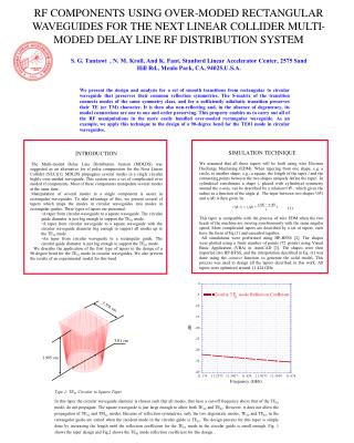
A Multi-Moded Delay Line RF Distribution System for the Next Linear Collider Sami G. Tantawi SLAC
Motivation • The Current Next Linear Collider design have accelerator structure sections that requires a 200 MW, 375 nS pulses at 11.424 GHz. The available power supplies are 75 MW klystrons which produces more than 1.5 mS pulses. Hence, pulse compression is needed.
Topics Discussed at ISG2 • Different Pulse Compression Techniques and Topologies • Component Development • Joint Experimental Work • High Power Experiments
TE01 TE12 (Vertically Polarized) TE12 (Horizontally Polarized) ~12.7 cm Circular Waveguide TE01 TE12 (Vertically Polarized) Klystrons ~7.4 cm Circular Waveguide TE01 Mode Extractor (Power is Extracted Evenly Between Four Waveguides) TE01 Mode Extractor TE01 Accelerator Structure (~1.8 m) TE21 Mode Launcher (Fed by Four Rectangular Waveguides) ~ 6 m TE01 Mode Converter (Fed by Four Rectangular Waveguides) TE01 Tap-Off TE12 to TE01 Mode Converter TE21-TE01 Mode Converter ~53 m
RF Power Sources RF A Cluster of 9 Multi-Moded DLDS Sections e+ or e- Eight 75-megawatt klystrons Delay Lines Accelerator Structures A Single Multi-Moded Delay Line RF Distribution System
TE01 Launcher TE01 Launcher TE11 Launcher Both Polarizations of TE11 TE01 2” TE01 Modular Launcher
TE12-TE11 Mode Converter TE11-TE01 Mode Converter TE12-TE11 Mode Converter 5” TE01 Mode Extractor
Extraction of The TE01 is done with the help of a “wrap-around mode converter”. The circular guide is tapered down to cutoff the TE01 mode while allowing the TE11 Mode to go through
Instead of using a cutoff section to allow the extraction of the TE01 mode, one can use two mode converters cascaded together
A short circuit Y0=1 Y0=1 Y0=1 Port 3 Port 2 Y0=1 Y0=1 Port 1 Port 4 Y0=1 Y0=1 Y0=1 If a signal is injected in port 1, it will all appear in port 3.
TE12-TE01 Mode Converter TE01 Mode Extractor Compact Mode Extractor
TE01 TE12 (Vertically Polarized) TE12 (Horizontally Polarized) ~12.7 cm Circular Waveguide ~ 6 m TE01 TE12 (Vertically Polarized) Klystrons ~7.4 cm Circular Waveguide TE01 Mode Extractor TE01 Mode Extractor (Power is Extracted Evenly Between Four Waveguides) TE01 TE01 Mode Converter (Fed by Four Rectangular Waveguides) TE01 Tap-Off TE12 to TE01 Mode Converter TE21-TE01 Mode Converter TE21 Mode Launcher (Fed by Four Rectangular Waveguides) SLAC KEK
Pump-Out/Flange 4.75” Waveguide TE11-TE12 Mode Converter 55 m TE11-TE10 Circular Taper Mode Analyzer Purpose of Experiment * Determine the attenuation of TE12 mode in Circular Waveguides. * Determine the stability of the TE12 mode.
High Power RF Sources and SystemsYong Ho Chin, Sami G. Tantawi, and Arnold E. Vlieks
Two DLDS are under development. 2x2 DLDS at KEK 3x1 DLDS at SLAC Both systems uses the same set of components. While the 3x1 requires a slightly more complicated extractor, it uses less waveguide. The 2x2 is slightly more efficient and can handle the mode rotation problem better
Components needed for both systems Launchers A common design for the launcher was adapted by both KEK and SLAC, We both produced a cold test model. SLAC model had one degree of freedom and produced a 98% effivient device KEK model had two degrees of freedum and produced a system that khas an efficiency of better than 99% A launcer based on circular to rectangular tapers is being devolped at SLAC
Extractors An extraction system based on wrap around-mode converter is due to be delivered at KEK shortly The serpentine mode converter part has been delivered and test An extractor based on the circular to rectangular taper is being devloped at SLAC
Tapers Compact tapers for circular waveguides has been desined and tested at SLAC Circular Linear tapers has been developed at KEK Mode-structure preserving Circular to Rectangular tapers have been developed at SLAC A type of Mode-Structure preserving Circular to square tapers has been devloped at KEK
Circular TE01 bends A bend based on circular to square tapers has been developed at SLAC A bend based on the same concept has been developed at KEK
Tap-offs A system of tap-offs have been developed at SLAC. The system is based on rectangular components and circular to rectangular tapers. Hybrids Two types of H-Plane over moded hybrids have been developed at SLAC. Both have a chance to withstand very high fields. High power loads A super High power load tree is developed at SLAC.
Alternative Pulse compression system Binary Pulse compression and active systems starts to be attractive at a higher Compression ratio. All the component development will fit into these systems There are some work on Circulators and Active switches, but it is still a premature art.
Mode Stability experiment Eerily April, After the PAC conference, a meeting at SLAC is going to take place to discuss the final preparation steps. All the basic components needed for the experiment are designed and most of it is ordered. A method for measuring a phase stable signal has been developed during the meeting by Y. Chin. The required instrumentation for this method is going to be discussed between now and April. The experiment most likely will take place in during the second half of July. However we may make it earlier because ATF is available all summer