3D Scanning
3D Scanning. Projection. How can we get the form?. Capturing design intents. Generators Fillet radius change Knuckles. Scanning. 3D Scanning is the process of getting a set of surface points from a physical object Touch probe, optical, laser ranging, etc.

3D Scanning
E N D
Presentation Transcript
Projection How can we get the form?
Capturing design intents • Generators • Fillet radius change • Knuckles
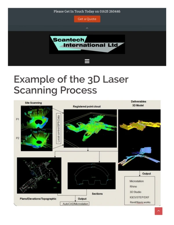
Scanning • 3D Scanning is the process of getting a set of surface points from a physical object • Touch probe, optical, laser ranging, etc. • Usually the points are structured
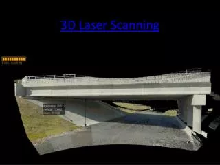
3D Scanning equipment • Contact type • Touch probe scanner • CMM • Non-contact type • Laser scanner • Optical scanner
Application range • From very small (tip of a drill bit) to very large (the Lee Ka Shing tower) • Rigid or soft • Coloured, glossy, transparent • Restrictions: Smoke, hair, cloud, very fast moving objects, etc.
Data captured • X Y Z location of points • Freshly scanned data sets are usually structured, as a array in XY plane with different Z values • May become un-structured, un-even spaced in all directions after re-sampling • Usually stored as an ASCII text file
Point cloud • The collection of points is called point clouds • A point cloud define the SURFACE of an object • Some scanner (like CT and MRI) can measure physical properties of a object’s entire solid mass, the collection of points is not point cloud, it is called VOXEL
Level of details (LOD) • LOD is determined by point density, which is determined during scanning • LOD is proportional to file size • Scanning itself is not selective, the result file size of a flat surface is the same as a carved board
Shape consideration • Optical scanner capture a 2D array of points each time • Steep surface will have less points cast on it, thus fewer details
Take ‘pictures’ of the object Output a set of 3D points 3D Optical scanning
Shape VS position • Point clouds gives only position information • The shape of the object, if there is any, is not defined in the point cloud data • Human can infer the shape from the clouds easily, but it is very difficult for machines
Scanning and stitching • Scan the object, coat the surface if necessary • If the scan result cannot cover entire surface, scan from other angles • Use point cloud manipulation software to align and merge scan results
Re-sampling • Re-sampling is the process to reduce the number of points or polygons so that the file size become manageable • Adaptive re-sampling reduce more data points on smooth surface and keep more in regions that have abrupt changes
Points are only x,y,z values Alignment
Positioning and scaling • Data from optical scanner is not necessary correct in size • Positioning of point cloud is not necessary suitable for surface patching • Alignment may need to be adjusted
Triangulation • The process of converting point clouds to polygon models • Triangulation is computation intensive • If two points are close together, they are most probably on one surface • If there are more that one possible shape, the shape that form a CONVEX HULL are more likely the correct choice
Feature curves • Feature curves are curves that define distinctive visual features • Sharp edges • Fillets • Holes • 3D scanning cannot capture feature curves directly • Irregularities may be corrected
Surface modelling • Generate surface patches using feature curves as guide lines • Lofting is easier but may generate surfaces with unwanted undulation • Sweeping and ruling generate fair surfaces but the feature curves are more difficult to draw • Irregularities may be corrected
Surface recreation • Cut Sections by user defined plane, and then create surface according to these sections • ‘Draw’ 3D feature curves directly on the point cloud • Full auto generation
Steps to retrieve CAD from foam model • Scanning and stitching • Re-sampling • Automatic surfacing or manual surfacing • For manual surfacing • Positioning and scaling • Draw feature curves • Draw Surface patches • Check deviation
Related applications • Specialised applications • Surfacer • Rapid Form • Raindrop Geomagic • Scanning modules • Pro/E, UG, CATIA, ALIAS