Download
1 / 35
360 likes | 600 Vues
Activity-Sensitive Flip-Flop and Latch Selection for Reduced Energy. Seongmoo Heo, Ronny Krashinsky, Krste Asanovi ć MIT - Laboratory for Computer Science http://www.cag.lcs.mit.edu/scale ARVLSI March 15, 2001. Flip-Flop and Latch (collectively timing elements).

E N D
Activity-Sensitive Flip-Flop and Latch Selection for Reduced Energy Seongmoo Heo, Ronny Krashinsky, Krste Asanović MIT - Laboratory for Computer Science http://www.cag.lcs.mit.edu/scale ARVLSI March 15, 2001
Flip-Flop and Latch(collectively timing elements) • Critical Timing Elements (TEs) in modern synchronous VLSI systems • Significant impact on cycle time • Big portion of energy consumption Energy breakdown of a MIPS 5 stage pipeline datapath for SPECint 95 programs Flip-flop Latch [Heo, MS Thesis, ’00]
Motivation • Previous work tried to find the most energy-efficient and fastest TEs • assuming a single TE design used uniformly throughout a circuit. • using a very limited set of data patterns and un-gated clock signal. • Two important observations • There is a wide variation in clock and data activity across different TEs. • Many TEs are not in the critical path, and thus have ample time slack.
Basic Idea • Selection from a heterogeneous library of designs, each tuned to different operating regimes • Operating regimes : • Different input and clock signal activities • Different speed requirements
Related Work • The use of timing slack for reduced energy • Examples : - Traditional transistor sizing - Cluster voltage scaling [Usami and Horowitz ’95] - Multiple threshold voltage or series transistor for reducing leakage current [McPherson et al. ’00, Yamashita et al. ’00, Johnson et al. ’99]
Our Contribution • Detailed energy characterization of wide range of TEs as a function of signal activities. • Detailed measurement of TE signal activities for a micro-processor running complete programs • Exploit signal activity to reduce TE energy by using different TE structures.
Overview • Flip-Flop and Latch Designs • Test Bench and Simulation Setup • Delay and Energy Characterization • Energy Analysis with Test Waveforms • Evaluation with Processor • Conclusion
Latch Designs Transistor sizes optimized for two extremes: Highest speed vs. Lowest power
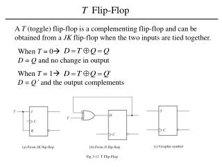
Flip-Flop Designs Transistor sizes optimized for two extremes: Highest speed vs. Lowest power
Flip-Flop Designs Transistor sizes optimized for two extremes: Highest speed vs. Lowest power
Flip-Flop Designs Transistor sizes optimized for two extremes: Highest speed vs. Lowest power
Flip-Flop Designs Transistor sizes optimized for two extremes: Highest speed vs. Lowest power
Flip-Flop Designs Transistor sizes optimized for two extremes: Highest speed vs. Lowest power
Flip-Flop Designs Transistor sizes optimized for two extremes: Highest speed vs. Lowest power
Test Bench • Used fixed, realistic input driver • Determined appropriate output load • As large as 200fF output load was used by previous work. • We used 7.2fF (4 min-inv cap) because 60% of output loads in the VP microprocessor datapath are smaller than 14.4fF. • Further work on load-sensitive analysis at upcoming WVLSI • Sized clock buffer to give equal rise/fall time 7.2fF
Simulation Setup • Custom layout in 0.25μm TSMC CMOS process with Magic layout program • Layout extraction with SPACE 2D extractor • Circuit simulation with Hspice under nominal condition of Vdd=2.5V and T=25°C • Hspice .Measure command to measure delay and energy
Delay Characterization • Flip-flop : Minimum D-Q delay [Stojanovic et al. ’99] • Latch : D-Q delay (a) Flip-flops (b) Latches
Energy Characterization • Total energy = input energy + internal energy + clock energy – output energy • Accurate energy characterization • State-transition technique based on [Zyuban and Kogge ’99] D Q C 1 1 2 3 2 3 C D Q
Energy Tables (a) Flip-flops (b) Latches
Energy Tables (a) Flip-flops (b) Latches
Test Waveforms • Test 1 and 2 : high clock activity, no data and output activity • Test 3 and 4 : high data activity, no clock and output activity • Test 5, 6, and 7 : high clock, data, and output activity (Traditional) • Test 8 : high clock and data activity, no output activity
Energy Analysis (a) Flip-flops 1131 (b) Latches Low-power flip-flops and latches
Processor Design and Simulation • Evaluation on a microprocessor datapath • Vanilla Pekoe Processor • A classic 32-bit MIPS RISC 5 stage pipeline with caches and system coprocessor registers (R3000-compatible) • Aggressive clock gating to save energy • 22 multi-bit flip-flops and latches, totaling 675 individual bits • Simulation with 5 programs of SPECint95 benchmarks • A fast cycle-accurate simulator [Krashinsky, Heo, Zhang, and Asanovic ’00] with the ability of counting TE state transitions • 1.71 billion instructions and 2.69 billion cycles • Some constraints • Cannot track the exact timing of signals • Cannot model glitches
Energy Breakdown (unit: mJ) (unit: mJ) • 32-bit MIPS 5 stage pipeline datapath • SPECint95 benchmarks: perl(test, primes), • ijpeg(test), m88ksim(test), • go(20,9), and lzw(medtest)
Energy Breakdown (unit: mJ) (unit: mJ) • 32-bit MIPS 5 stage pipeline datapath • SPECint95 benchmarks: perl(test, primes), • ijpeg(test), m88ksim(test), • go(20,9), and lzw(medtest)
Energy Breakdown (unit: mJ) (unit: mJ) • 32-bit MIPS 5 stage pipeline datapath • SPECint95 benchmarks: perl(test, primes), • ijpeg(test), m88ksim(test), • go(20,9), and lzw(medtest)
Processor Energy Results - Flip-Flop HS: Highest-Speed LP: Lowest-Power HLFF-hs (A single design used uniformly throughout a circuit) HLFF-lp SSAFF-hs SSASPL-hs SSAFF-lp SSASPL-lp • Ref : Total datapath energy – Total TE energy = around 0.21J
Processor Energy Results - Flip-Flop HLFF-hs 34% energy saving • 34% energy saving with conventional transistor sizing
Processor Energy Results - Flip-Flop HSLE: Activity-Sensitive selection HLFF-hs 69% energy saving 52% energy saving • 52% energy saving over just transistor sizing • with the best performance (HLFF-hs)
Processor Energy Results - Latch 1 2 PPCLA-hs SSA2LA-lp • 6.1% energy saving over just transistor sizing (1) • 8.3% energy saving compared to homogeneous design with PPCLA-hs (2) • PPCLA is the fastest and also very energy-efficient.
Summary of Energy Results • 63% TE energy saving compared to a homogeneous design with HLFF-hs and PPCLA-hs • 46% TE energy saving compared to a design with conventional transistor sizing while keeping the best performance
Conclusion • We showed that activation patterns for various TEs in a circuit differ considerably. • We found that there is wide variation in the optimal TE designs for different regimes. • We provided complete energy and delay characterization. • We applied our technique to a real processor which we simulated 2.7 billion cycles of programs and showed over 63% TE energy reduction without losing any performance. Difficulty of using a heterogeneous mix of TEs? - Already designers have been doing verification for each local clock and added complexity is minimal. - Timing verification for non-critical TEs is simple.