Friction Roller Identification
Friction Roller Identification. Jack Weatherford. Hermitage Automation & Controls. Application Description:.

Friction Roller Identification
E N D
Presentation Transcript
Friction Roller Identification Jack Weatherford HermitageAutomation & Controls
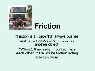
Application Description: During a robotic disassemble of a printer toner cartridge, a friction roller is removed for recovery or recycling. There are 3 possible rollers. The steel center shafts all have the same outside diameter (6.35 mm), but each have unique features. The vision system will inspect the shaft ends, and signal the robot’s controller (via digital outputs) as to which roller has been extracted. Roller Shaft A has a conical bore and large chamfer on both ends. Roller Shaft B has flat ends, each with a relatively large chamfer. Roller Shaft C has flat ends with a small chamfer.
Solution: A single VA-31vision appliance running iNspect was chosen for its processing speed. This particular customer has also standardized on the VA-31 as their vision platform. A red LED Diffused On Axis Light (DOAL) was used to eliminate the reflectivity of non-specular surfaces in the FOV. Only the ground, polished ends of the shafts are illuminated. Inspection Details: VA31 Vision Appliance Bundle w/single camera 50 mm C mount lens In addition, 15 mm of lens spacers were used to reduce the minimum focus distance of the lens. Northeast Robotics DOAL with 50 mm aperture, strobed. GardSoft PP600, strobe control unit Distance To Target (CCD to shaft end) = 250 mm
Software Tools: Preprocessing was applied to the camera images. Threshold filtered out some of the background and areas on the chamfers that reflected some light. Erosion and dilation were used to further filter noisy portions of the shaft ends.
Software Tools (cont.): In iNspect, a Count/Area tool is placed over a majority of the image in the Field Of View. After retrieving the roller from the cartridge, the inspection is triggered by the robot at a predetermined position along it’s path as it moves towards the collection bin area. Since the trigger position is fairly repeatable, and the area of the Count tool so large, no Location tool is needed.
Software Tools (cont.): The Count/Area properties are set to allow a wide range of blobs to be detected. Pass, Fail and Recycle settings were not used in this app. Values were set so that a major failure of the inspection could be signaled to the robot. From observations made during testing and setup, the shaft areas ranged from: 31900 up to 69100 Min/Max values for Area, Width and Height were set to accommodate this range.
Software Tools (cont.): To complete the setup, Outputs were defined. Equations in the Post Image Process panel set the outputs according to theArea reported by the Count tool. The 3 outputs - GPO[0],GPO[1] & GPO[2] will signal the controller as to which friction roller has been presented. Since these are latched outputs, they are first all set to OFF (0). 3 “if” statements are processed to determine which output will be turned on based on the reported Area of the Count tool. Acceptable ranges in the decision area are wide enough to determine the correct shaft (plus or minus some variation), but not enough to overlap. From observation during setup and testing: Shaft A area = 33650 +/- 1600 Shaft B area = 54500 +/- 2000 Shaft C area = 66500 +/- 2500
Remember! Blob Tools are your friend!