Download

1 / 41
470 likes | 986 Vues
PGY-1 CURRICULUM Basic Orthopaedic Skills. Indiana University School Medicine Department of Orthopaedic Surgery July, 2013. GOALS. Understand the indications for percutaneous pinning (PP) of fractures (fx)

E N D
PGY-1 CURRICULUMBasic Orthopaedic Skills • Indiana University School Medicine • Department of Orthopaedic Surgery • July, 2013
GOALS • Understand the indications for percutaneous pinning (PP) of fractures (fx) • Understand the indications for damage control orthopaedics and stabilization with external fixation (EF) devices • Understand the complications of EF and PP devices • Demonstrate the ability to use the small battery drive • Demonstrate the ability to place K-wires across a fx • Demonstrate the ability to place a simple EF construct
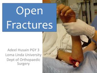
PERCUTANEOUS PINNING OF FRACTURES • The most common fx using percutaneous pinning is the pediatric supracondylar humerus fracture (types II and III) • It is the most common operative procedure in pediatric fxs • Jan 2004 – Dec 2011 – 297 cases of the most severe type III SCH fx rx’ed at Riley
PEDIATRIC SCH FX • Type I – non displaced • Type II – posterior cortex intact • Type III – completely displaced • All type II and IIIs rx’ed with CRPP
TODAY – LEARN HOW TO PIN THE FX AFTER REDUCTION • Learn to use the battery driver • Understand K wire and Steinmann pin size • Understand the best mechanical configuration for CRPP • Understand the concerns for cross pinning • Demonstrate appropriate skill in pinning
K-WIRES AND STEINMANN PINS • Are the same , differentiated by size • K wires – 0.028" (0.7mm) diameter 0.035" (0.9mm) diameter • 0.045" (1.1mm) diameter • 0.054" (1.4mm) diameter • 0.062" (1.6mm) diameter • Steinmann pins – • Range from 5/64” (2.0mm) to3/16” (4.8mm) in increments of 1/64”
K-WIRES AND STEINMANN PINS • Trocar or diamond end • Smooth or threaded • Single or double
GENERAL CONCEPTS WITH PERCUTANEOUS FX PINNING • The drill is typically battery powered • Can use either quick release or Jacob’s chuck • For PP of fx using with smaller pins I recommend a quick release chuck
DRILL CHUCKS • Jacob’s chuck – the standard wood shop chuck using a key to tighten it • Quick release – the chuck grabs the wire by simply squeezing the handle
PLACE THE PIN IN THE CHUCK • With quick release make sure the number of “dots” is the appropriate one for the pin size selected • Assure the quick release is working properly and make sure it is powered before even starting the fixation!!!
START THE PIN FIXATION • Start perpendicular to the bone • When necessary, begin to angle the drill/wire after entering the bone – in a gradual manner • Do not bend the pin!
RADIOGRAPHIC ASSESSMENT • Start the pin under radiographic control to ensure appropriate direction • Monitor frequently - both AP and lateral • As you acquire more experience, the amount of imaging will become less
PIN CONFIGURATION • Biomechanically, cross pin fixation better • However it is associated with a significant increase in iatrogenic ulnar nerve injury – 1 in every 28 pts rx with cross pins will have an iatrogenic ulnar N injury!! • Multiple pins using lateral entry are clinically equal to cross pin configuration • Cross pinning should be used in only the most unstable situation!!!!
TYPE III SCH FXPerfect Pinning! • All pins parallel/divergent • All pins engage both cortices on both AP and lateral views • No cross pins!!
NUMBER OF PINS • For lateral entry pinning 3 is the typical number • However do not be afraid to use the blow gun technique – 4 or 5 pins • Remember that an iatrogenic ulnar N injury is a significant event!
AFTER FIXATION • Extend the elbow to assess the carrying angle / cubitus varus • Assess the stability of the fixation under real time flouroscopy with flexion / extension of the elbow
EXTERNAL FIXATOR - TIBIA • Today - • Identify the components in the large ex fix set • Review the steps for the assembly of a frame • Make sense of the “tinker toys”
EXTERNAL FIXATORIndications • Trauma • Open Fractures • Severe soft tissue injury • Comminution • Bone loss • Temporizing or Definitive
DAMAGE CONTROL ORTHOPAEDICS • Applies to the polytraumatized patient • 3 main stages • Early temporary stabilization of unstable fxs, control of hemorrhage, and decompression intracranial lesion • Resuscitation of pt in ICU and optimization • Delayed definitive management of fxs
EXTERNAL FIXATOR Advantages • Simplicity and ease of application • Minimal blood loss • Adjustability after surgery • Access for wound management
EXTERNAL FIXATORDisadvantages • Anatomic structures at risk (Safe Zones) • Pin/Wire site infections • Joint contractures • Prolonged time to bony healing
EXTERNAL FIXATOR - TIBIA • Simple: • Clamps • Bars • Pins
TERMINOLOGY • Bars, Rods and Tubes are used interchangeably • bars & rods are solid • tubes are hollow • Pins & Schanz Screws • same
EX FIX CLAMPS • Connects pins to rods
EX FIX CLAMPS • Combination clamps – connects • Pins to rods • Rods to rods
EX FIX PINS/CLAMPS • Large clamps accommodate 4.0mm to 6.0mm Schanz Screws 4.0 mm for Small Ex Fix 4.5 & 5.0 mm for tibia and pelvis 6.0 mm for femur and large distractor
INSERTING PINS • Select site under flouroscopy • Small longitudinal incision • Hemostat down to bone • Then use the trocar and sleeves • Drilling and pin tract/insertion should be perpendicular to bone
SAFETY FACTORS • Pin/Wire should not • be in the fracture • When drilling go slow as not to burn the bone
STABILITY FACTORS Pin/Wire Location Maximal pin span More pins distribute forces and increase construct stiffness
STABILITY FACTORS • Lower Bone-Rod distance increases stiffness • In-line stacking • increases stiffness • Second sidebar at 90o to first increases stiffness
STABILITY FACTORS • Pin/Wire Size • Torsional strength proportional to its radius4 • Pin core diameter • < • 1/3 bone diameter
STABILITY FACTORS • Insertion Technique • Thread-Shank junction • is weakest point • Insert pin shank to • proximal cortex • (2x increased stiffness) • (threads = bone width) • Off plane pin insertion
INSERTING PINS • To insert pins: • Trocar & 2 sleeves • 3.5mm drill bit • Irrigate to prevent heat & pin loosening ! 3.5mm inner sleeve for 3.5mm drill bit 5.0mm outer sleeve for Schanz screw Trocar
INSERTING PINS • Chuck with T handle through outer sleeve • Advance to proper depth, just engaging opposite cortex – both a feel and radiographically confirmed
ADDING RODS/CLAMPS Use 11mm cannulated socket wrench or ratchet wrench Need 2 of each for surgeon and assistant Then reduce fracture - flouroscopic control
PIN CUTTERS AND PROTECTORS • Protects contralateral extremity and allows patient movement
Spanning External Fixators • Portable Traction • Span intra-articular fracture • Aide reduction through ligamentotaxis