Download
1 / 15
150 likes | 348 Vues
1487. 1491. 1400. 1320. 1322. 1342. 1316. 1445. 1326. 1344. 1410. 1455. 1560. 1206. Ladder Wiring Diagram. +120V. -120V. NOTES: 1. Wire Labeling 2 – AC Neutral 100 – L1 200 – L2 24 – 24V 2402 – 24 COM 10 – 10V 1002 – 10V COM 2. Line Numbering

E N D
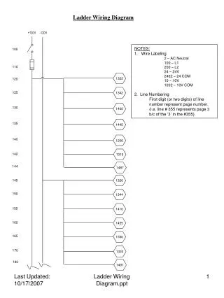
1487 1491 1400 1320 1322 1342 1316 1445 1326 1344 1410 1455 1560 1206 Ladder Wiring Diagram +120V -120V • NOTES: • 1. Wire Labeling • 2 – AC Neutral • 100 – L1 • 200 – L2 • 24 – 24V • 2402 – 24 COM • 10 – 10V • 1002 – 10V COM • 2. Line Numbering • First digit (or two digits) of line number represent page number. • (i.e. line # 355 represents page 3 b/c of the ‘3’ in the #355) 100 110 120 125 130 135 140 142 144 145 150 155 160 165 170 180 Ladder Wiring Diagram.ppt
G 245 - + 24 V POWER SUPPLY - 200 + E-STOP SAFETY MODULE E-STOP #1 (control box) E-STOP #2 (podium) 210 A1 A2 215 START 217 220 S33 S11 225 S21 230 235 S22 240 S12 217 245 13 250 14 690 255 260 1005 23 265 1338 24 270 1015 33 275 1354 34 280 Ladder Wiring Diagram.ppt
SLOT #1 DIGITAL INPUT 1746-IB16 LS_WING 300 I / 1:0 LS_SUPPORT 305 I / 1:1 STR8 LINE MOTION 310 I / 1:2 RESTRICTED MODE I / 1:3 315 UNRESTRICTED MODE 320 I / 1:4 4 POSITION DEMO MODE 325 I / 1:5 TEACH MODE I / 1:6 330 ‘BEGIN’ BUTTON I / 1:7 335 ‘END’ BUTTON 340 I / 1:8 ‘RECORD’ BUTTON I / 1:9 345 MOTION SENSOR 1302 I / 1:10 350 GRIPPER CLOSE I / 1:11 355 2 POSITION TOGGLE GRIPPER OPEN 360 I / 1:12 MOVE Z+ 365 I / 1:13 2 POSITION TOGGLE MOVE Z- 370 I / 1:14 MOVE X+ 375 I / 1:15 380 DC COM 385 DC COM Ladder Wiring Diagram.ppt
SLOT #2 DIGITAL INPUT 1746-IB16 4 POSITION JOYSTICK MOVE X- 400 I / 2:0 MOVE Y+ 405 I / 2:1 MOVE Y- 410 I / 2:2 LS_J1_HOME 415 I / 2:3 LS_J1_AWAY 420 I / 2:4 LS_J2_HOME I / 2:5 425 LS_J2_AWAY 430 I / 2:6 LS_J3_HOME 435 I / 2:7 LS_J3_AWAY 440 I / 2:8 LS_J4_HOME I / 2:9 445 LS_J4_AWAY 450 I / 2:10 LS_J5_HOME 455 I / 2:11 LS_J5_AWAY I / 2:12 460 LS_GRIPPER_OPEN I / 2:13 465 I / 2:14 470 I / 2:15 475 480 DC COM 485 DC COM Ladder Wiring Diagram.ppt
SLOT #3 DIGITAL INPUT 1746-IB16 4 POSITION JOYSTICK GRIPPER_PITCH_UP 500 I / 3:0 GRIPPER_PITCH_DWN 505 I / 3:1 GRIPPER_CW 510 I / 3:2 GRIPPER_CCW I / 3:3 515 LS_GRIPPER_CLOSE 520 I / 3:4 I / 3:5 525 530 I / 3:6 535 I / 3:7 540 I / 3:8 545 I / 3:9 550 I / 3:10 555 I / 3:11 I / 3:12 560 I / 3:13 565 I / 3:14 570 I / 3:15 575 580 DC COM 585 DC COM Ladder Wiring Diagram.ppt
SLOT #4 1262 1114 1146 1246 1214 1230 1130 1162 DIGITAL OUTPUT 1746-OV16 G Y R 24 VDC 600 O / 4:0 605 610 O / 4:1 615 O / 4:2 620 O / 4:3 O / 4:4 625 630 O / 4:5 O / 4:6 635 O / 4:7 640 O / 4:8 645 O / 4:9 650 O / 4:10 655 O / 4:11 660 665 O / 4:12 O / 4:13 670 O / 4:14 680 O / 4:15 685 255 690 DC COM Ladder Wiring Diagram.ppt
1489 1495 SLOT #5 700 ANALOG INPUT 1746-NI8 702 SHIELD J1_POT 704 706 I / 4:0+ 708 J2_POT I / 4:0- 710 712 I / 4:1+ 714 I / 4:1- J3_POT 716 718 I / 4:2+ J4_POT 720 I / 4:2- 722 724 I / 4:3+ 726 J5_POT I / 4:3- 728 730 I / 4:4+ 732 I / 4:4- I / 4:5+ 734 I / 4:5- 736 I / 4:6+ 738 740 I / 4:6- 742 I / 4:7+ 744 I / 4:7- SHIELD 746 748 Ladder Wiring Diagram.ppt
SLOT #6 ANALOG OUTPUT 1746-N04V 800 24V+ 810 COM 1334 820 O / 6:0 1340 830 COM 1352 840 O / 6:1 1356 850 COM 1430 860 O / 6:2 1435 870 COM 1480 880 O / 6:3 1485 890 COM 748 Ladder Wiring Diagram.ppt
SLOT #7 BASIC MODULE 1746-BAS 900 PRT1 (RS-232) 910 PRT2 (RS-232) 920 DH-485 Ladder Wiring Diagram.ppt
265 275 SLOT #8 RELAY OUTPUT 1746-OW16 1356 1340 V1+ 1000 1005 O / 8:0 1010 O / 8:1 1015 O / 8:2 O / 8:3 1020 1025 O / 8:4 O / 8:5 1030 1035 O / 8:6 O / 8:7 1040 V2+ 1045 O / 8:9 1050 1055 O / 8:8 O / 8:11 1060 1065 O / 8:10 O / 8:13 1070 1075 O / 8:12 O / 8:15 1080 O / 8:14 1085 Ladder Wiring Diagram.ppt
1158 1540 1530 1126 1154 1122 1185 1126 1154 1122 Motor #3 Direction Relay 2 1102 3 1104 1405 1 1106 4 1108 1415 8 1110 5 1112 650 1114 7 6 1116 Motor #3 Power Relay 1118 2 3 1120 1108 1116 1122 1 1124 4 1104 1112 1126 8 5 1128 605 1130 7 1535 6 1132 Motor #4 Direction Relay 2 1134 3 1136 1 1138 4 1140 8 1142 5 1144 655 7 1146 6 1148 Motor #4 Power Relay 2 1150 3 1152 1140 1148 1154 1 4 1156 1136 1144 8 1158 5 1160 610 1162 7 1550 6 1164 Ladder Wiring Diagram.ppt
1555 1570 1258 1226 1254 1222 1258 1226 1254 1222 Motor #5 Direction Relay 2 1202 3 1204 140 1 1206 4 1208 8 1210 5 1212 620 1214 7 6 1216 Motor #5 Power Relay 1218 2 3 1220 1208 1216 1222 1 1224 4 Capacitor 1212 1204 1226 8 5 1228 615 1230 7 1565 6 1232 Motor #6 Direction Relay 2 1234 3 1236 1493 1 1238 4 1240 1497 8 1242 5 1244 630 7 1246 6 1248 Motor #6 Power Relay 2 1250 3 1252 1240 1248 1254 1 4 1256 1244 1236 8 1258 5 1260 625 1262 7 1575 6 1264 Ladder Wiring Diagram.ppt
1510 350 120 145 125 150 840 280 1515 1000 1525 700 1505 1500 748 270 820 1520 Motion Sensor Relay 1318 2 1300 3 1302 1304 1 This component was not installed as of 10/5/2007 1306 4 1308 8 5 1310 1320 1312 7 1314 6 Motion Sensor This component was not installed as of 10/5/2007 142 1316 L1 1300 1318 SIGNAL 170 L2 1320 GND VFD #1 - (Motor #1) 1322 L1 1324 T1 L2 1326 1328 T2 GND 1332 T3 1334 AI +10V 1336 1338 DF1 GND 830 1000 COM 1340 VFD #2 – (Motor #2) L1 1342 T1 1344 1346 L2 1348 T2 GND T3 1350 1352 AI GND 1354 DF1 850 1356 COM Ladder Wiring Diagram.ppt
130 1142 1138 890 880 160 700 748 135 860 870 1106 1110 144 180 155 DC MOTOR CONTROLLER #1 (Motor #3) 1400 L1 1405 ARM + 1410 L2 1415 ARM - 1420 GND 1430 WIPER GND 1435 POT LO 1440 DC MOTOR CONTROLLER #2 (Motor #4) 1445 L1 1450 ARM + 1455 L2 1460 ARM - This component was not installed as of 10/17/2007 1465 GND 1470 GND WIPER 1480 POT LO 1485 10VDC POWER SUPPLY L1 1487 10VDC+ 1489 1491 L2 1238 1493 GND 10VDC- 1495 1497 1242 Ladder Wiring Diagram.ppt
Motor #5 Motor #1 Motor #2 1325 1328 1332 1344 1405 1348 1350 165 1415 1450 1460 1252 1264 1220 1232 1500 AC 1505 1510 1515 AC 1520 1525 1530 DC Motor #3 1535 1540 DC Motor #4 1550 1555 AC 1560 1565 1570 DC Motor #6 1575 END Ladder Wiring Diagram.ppt