Electromagnetic Waves: Energy, Pressure, and Reflection
Explore the energy and pressure aspects of electromagnetic waves, including Maxwell's equations, energy densities, Poynting vector, wave momentum, radiation pressure, and polarization. Discover how EM waves propagate and carry energy. Learn how to calculate radiation pressure and optical phenomena relating to polarization.

Electromagnetic Waves: Energy, Pressure, and Reflection
E N D
Presentation Transcript
Electromagnetic Waves Chapter 34, sections 4-9 Energy and pressure Polarization Reflection and Refraction
Maxwell’s Equations in a Vacuum Consider these equations in a vacuum: no charges or currents
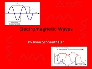
E(x, t) = EP sin (kx-t) B(x, t) = BP sin (kx-t) ˆ j ˆ z Solved by: Plane Electromagnetic Waves Ey Bz Works for any wavelength l=2p/k as long as c x Since w=2pf and k=2p/l, this means lf=c. l is inversely proportional to f.
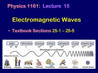
The Electromagnetic Spectrum infra -red ultra -violet Radio waves g-rays m-wave x-rays
Energy in Electromagnetic Waves • Electric and magnetic fields contain energy, the potential energy stored in the field: • uE= (1/2)0 E2electric field energy density • uB= (1/20) B2 magnetic field energy density • The energy is put into the oscillating fields by the sources that generate them. • This energy then propagates to locations far away, at the velocity of light.
Energy in Electromagnetic Waves B dx area A E c propagation direction
Energy in Electromagnetic Waves Energy per unit volume in an EM wave: u = uE + uB B dx area A E c propagation direction
Energy in Electromagnetic Waves Energy per unit volume in an EM wave: u = uE + uB Thus the energy dU in a box of area A and length dx is B dx area A E c propagation direction
Energy in Electromagnetic Waves Energy per unit volume in an EM wave: u = uE + uB Thus the energy dU in a box of area A and length dx is Let the length dx equal cdt. Then all of this energy flows through the front face in time dt. Thus energy flows at the rate B dx area A E c propagation direction
Energy in Electromagnetic Waves B Rate of energy flow: dx area A E c propagation direction
Energy in Electromagnetic Waves B Rate of energy flow: dx area A E We define the intensityS as the rate of energy flow per unit area: c propagation direction
Energy in Electromagnetic Waves B Rate of energy flow: dx area A E We define the intensityS, as the rate of energy flow per unit area: c propagation direction Rearranging by substituting E=cB and B=E/c, we get
The Poynting Vector In general we write: S = (1/0)Ex B Sis a vector that points in the direction of propagation of the wave and represents the rate of energy flow per unit area. We call this the “Poynting vector”. Units of S are Jm-2 s-1, or Watts/m2. B dx area A E propagation direction
The Poynting Vector For a plane EM wave the intensity is
The Poynting Vector For a plane EM wave the intensity is Because the fields depend on position and time, so does the intensity:
The Poynting Vector For a plane EM wave the intensity is Because the fields depend on position and time, so does the intensity: If you sit at a certain position S will change in time. The average is _ Sometimes the notation S is used for Savg.
r Source Poynting vector for spherical waves A point source of light, or any EM radiation, spreads out as a spherical wave: Power, P, flowing through sphere is same for any radius. Source
Example:An observer is 1.8 m from a point light source whose average power P= 250 W. Calculate the rms fields in the position of the observer. Intensity of light at a distance r is S= P / 4pr2
Wave Momentum and Radiation Pressure It is somewhat surprising to discover that EM radiation possesses momentum as well as energy. The momentum and energy of a wave are related by p = U / c.
Wave Momentum and Radiation Pressure It is somewhat surprising to discover that EM radiation possesses momentum as well as energy. The momentum and energy of a wave are related by p = U / c. If light carries momentum then it follows that a beam of light falling on an object exerts a pressure: Force = dp/dt = (dU/dt)/c Pressure (radiation) = Force / unit area P = (dU/dt) / (A c) = S / c Radiation Pressure
Example: Serious proposals have been made to “sail” spacecraft to the outer solar system using the pressure of sunlight. How much sail area must a 1000 kg spacecraft have if its acceleration is to be 1 m/s2 at the Earth’s orbit? Make the sail reflective. Can ignore gravity. Need F=ma=(1000kg)(1 m/s2)=1000 N This comes from pressure: F=PA, so A=F/P. Here P is the radiation pressure of sunlight: Sun’s power = 4 x 1026 W, so S=power/(4pr2) gives S = (4 x 1026 W) / (4p(1.5x10¹¹m)2 )= 1.4kW/m2. Thus the pressure due to this light, reflected, is: P = 2S/c = 2(1400W/m2) / 3x10⁸m/s = 9.4x10⁻⁶N/m2 Hence A=1000N / 9.4x10⁻⁶N/m2 =1.0x10⁸ m2 = 100 km2
Ey Bz x Polarization The direction of polarization of a wave is the direction of the electric field. Most light is randomly polarized, which means it contains a mixture of waves of different polarizations. Polarization direction
Polarization A polarizer lets through light of only one polarization: E Transmitted light has its E in the direction of the polarizer’s transmission axis. E0 q E = E0cosq hence S = S0cos2q Malus’s Law If the initial beam has bits with random polarizations, then S = S0(cos2q)avg= S0/2: half gets through.
Geometrical Optics • Optics is the study of the behavior of light (not necessarily visible light). • This behavior can be described by Maxwell’s equations. • However, when the objects with which light interacts are larger that its wavelength,the light travels in straight lines called rays, and its wave nature can be ignored. • This is the realm of geometrical optics. • The wave properties of light show up inphenomena such as interference and diffraction.
This can be described using geometrical optics This requires the use of full wave optics (Maxwell’s equations) Geometrical Optics Light can be described using geometrical optics, as long as the objects with which it interacts are much larger than the wavelength of the light.
Reflection and Transmission Some materials reflect light. For example, metals reflect light because an incident oscillating light beam causes the metal’s nearly free electrons to oscillate, setting up another (reflected) electromagnetic wave. Opaque materials absorb light (by, say, moving electrons into higher atomic orbitals). Transparent materials are usually insulators whose electrons are bound to atoms, and which would require more energy to move to higher orbitals than in materials which are opaque.
q1 Geometrical Optics q1 = angle of incidence Normal to surface Incident ray Surface Angles are measured with respect to the normal to the surface
Reflection q1 q’1 The Law of Reflection: Light reflected from a surface stays in the plane formed by the incident ray and the surface normal; and the angle of reflection equals the angle of incidence (measured to the normal) q1 = q’1 This is called “specular” reflection
Medium 1 q’1 q1 Medium 2 q2 Refraction More generally, when light passes from one transparent medium to another, part is reflected and part is transmitted. The reflected ray obeys q1 = q’1.
Medium 1 q’1 q1 Medium 2 q2 Refraction More generally, when light passes from one transparent medium to another, part is reflected and part is transmitted. The reflected ray obeys q1 = q’1. The transmitted ray obeys Snell’s Law of Refraction: It stays in the plane, and the angles are related by n1sinq1 = n2sinq2 Here n is the “index of refraction” of a medium.
Medium 1 q’1 q1 Reflected ray Medium 2 Incident ray Refracted ray q2 Refraction q1= angle of incidence ’1=angle of reflection q1 = angle of refraction Law of Reflection q1= ’1 Law of Refraction n1 sin1= n2 sin2 nindex of refraction ni = c / vi vi = velocity of light in medium i
Refraction l1=v1T The period T doesn’t change, but the speed of light can be different. in different materials. Then the wavelengths l1 and l2 are unequal. This also gives rise to refraction. q1 1 q1 2 q2 l2=v2T The little shaded triangles have the same hypotenuse: so l1/sinq1= l2/sinq2, or v1/sinq1=v2/sinq2 q2 Define the index of refraction: n=c/v. Then Snell’s law is: n1sinq1 = n2sinq2
Example: air-water interface If you shine a light at an incident angle of 40o onto the surface of a pool 2m deep, where does the beam hit the bottom? Air: n=1.00 Water: n=1.33 (1.00)sin40 = (1.33)sinq sinq=sin40/1.33 so q=28.9o Then d/2=tan28.9o which gives d=1.1 m. 40 air water 2m q d
Example: air-water interface If you shine a light at an incident angle of 40o onto the surface of a pool 2m deep, where does the beam hit the bottom? Air: n=1.00 Water: n=1.33 (1.00)sin40 = (1.33)sinq sinq=sin40/1.33 so q=28.9o Then d/2=tan28.9o which gives d=1.1 m. 40 air water 2m q d
Example: air-water interface If you shine a light at an incident angle of 40o onto the surface of a pool 2m deep, where does the beam hit the bottom? Air: n=1.00 Water: n=1.33 (1.00) sin(40) = (1.33) sinq Sinq = sin(40)/1.33 so q = 28.9o Then d/2 = tan(28.9o) which gives d=1.1 m. 40 air water 2m q d Turn this around: if you shine a light from the bottom at this position it will look like it’s coming from further right.
1 air water q2 Air-water interface Air: n1 = 1.00 Water: n2 = 1.33 n1 sin1 = n2 sin2 n1/n2 = sin2 / sin1 When the light travels from air to water (n1 < n2) the ray is bent towards the normal. When the light travels from water to air (n2 > n1) the ray is bent away from the normal. This is valid for any pair of materials with n1 < n2
Total Internal Reflection • Suppose the light goes from medium 1 to 2 and that n2<n1 (for example, from water to air). • Snell’s law gives sin q2 = (n1 / n2) sin q1. • Sincesin q2 <= 1there must be a maximum value of q1. • At angles bigger than this “critical angle”, the beam is totally reflected. • The critical angle is when q2=p/2, which gives qc=sin-1(n2/n1).
Total Internal Reflection n1 > n2 q2 n2 q2 q1 qc q1 q1 n1 n2sin p/2 = n1sinq1 ... sinq1 = sinqc = n2 /n1 Total internal reflection: no light is refracted Some light is refracted and some is reflected
Example: Fiber Optics An optical fiber consists of a core with index n1 surrounded by a cladding with index n2, with n1>n2. Light can be confined by total internal reflection, even if the fiber is bent and twisted. Exercise: For n1 = 1.7 and n2 = 1.6 find the minimum angle of incidence for guiding in the fiber. Answer:sin qC = n2 / n1 qC = sin-1(n2 / n1) = sin-1(1.6/1.7) = 70o. (Need to graze at < 20o)
n 1.55 1.53 1.51 400 500 600 700 nm Dispersion The index of refraction depends on frequency or wavelength: n = n(l ) Typically many optical materials, (glass, quartz) have decreasing n with increasing wavelength in the visible region of spectrum Dispersion by a prism: 700 nm 400 nm
1 red violet Example: dispersion at a right angle prism Find the angle between outgoing red (r = 700nm) and violet (v = 400nm) light [ n400 =1.538, n700 = 1.516, 1 = 40° ]. 2 n1 sin1 = n2 sin2 n2 = 1 (air) Red: 1.538 sin(40°) = 1 sin400 400 = sin-1(1.538 0.643) = 81.34° Violet: 1.516 sin(40°) = 1 sin700 700 = sin-1(1.516 0.643) = 77.02° = 4.32° angular dispersion of the beam
TI I RI Reflection and Transmission at Normal Incidence Geometrical optics can’t tell how much is reflected and how much transmitted at an interface. This can be derived from Maxwell’s equations. These are described in terms of the reflection and transmission coefficients R and T, which are, respectively, the fraction of incident intensity reflected and transmitted. For the case of normal incidence, one finds: Notice that when n1=n2 (so that there is not really any interface), R=0 and T=1.
Reflection and Transmission at Oblique Incidence In this case R and T depend on the angle of incidence in a complicated way – and on the polarization of the incident beam. We relate polarization to the plane of the three rays. E parallel incident reflected n1 E perpendicular n2 transmitted
Reflection and Transmission at Oblique Incidence Light with the perpendicular polarization is reflected more strongly than light with the parallel polarization. Hence if unpolarized light is incident on a surface, the reflected beam will be partially polarized. R (%) 100 50 perp parallel 10 20 30 40 50 60 70 80 90 Angle of incidence Notice that at grazing incidence everything is reflected.
Reflection and Transmission at Oblique Incidence qp 100 Polarizing angle, or “Brewster’s angle” 50 R (%) perp parallel 10 20 30 40 50 60 70 80 90 Angle of incidence Brewster’s angle of incidence is the angle at which light polarized in the plane is not reflected but transmitted 100%All the reflected light has perpendicular polarization.