Download
1 / 66
660 likes | 754 Vues
Explore the basics and hybrid LAN topologies, backbone structures, switching types, and Ethernet standards in this informative guide. This chapter delves into physical topologies like bus, ring, star, and their characteristics, advantages, and disadvantages. Learn about logical topologies, backbone networks, and how nodes share a communications channel on Ethernet networks. Gain insights into various terminologies and configurations in network design.

E N D
Network+ Guide to Networks6th Edition Chapter 5 Topologies and Ethernet Standards
Objectives • Describe the basic and hybrid LAN topologies, and their uses, advantages, and disadvantages • Describe the backbone structures that form the foundation for most networks • Compare the different types of switching used in data transmission • Explain how nodes on Ethernet networks share a communications channel • Identify the characteristics of several Ethernet standards Network+ Guide to Networks, 6th Edition
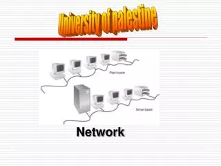
Simple Physical Topologies • Physical topology: physical layout of the media, nodes, and devices on a network • It does not specify: • Device types • Connectivity methods • Addressing schemes • Fundamental shapes • Bus, ring, star • Hybrid Network+ Guide to Networks, 6th Edition
Bus • Bus topology • Single cable • Connects all network nodes • No intervening connectivity devices • One shared communication channel (bus) • Physical medium • Coaxial cable (Thinnet & Thicknet) • Passive topology: each node passively listens for, then accepts, data directed to it • Uses broadcast to alert other nodes that a transmission is being sent Network+ Guide to Networks, 6th Edition
Bus (cont’d.) • Terminators • 50-ohm resistors • Stop signal at end of wire • Used to prevent signal bounce • Signal bounce • Signal travels endlessly between two network ends • One end grounded • Removes static electricity that could adversely affect the signal Network+ Guide to Networks, 6th Edition
Figure 5-1 A terminated bus topology network Courtesy Course Technology/Cengage Learning Network+ Guide to Networks, 6th Edition
Bus (cont’d.) • Bus topology advantage • Relatively inexpensive • Disadvantages • Does not scale well • Not very fault tolerant Network+ Guide to Networks, 6th Edition
Ring • Ring topology • Node connects to nearest two nodes • Circular network • Clockwise data transmission • One direction (unidirectional) around ring • Active topology: All workstations participates in data delivery (act as a repeater) vs. broadcasts (Bus) • Physical medium • Twisted pair or fiber-optic cabling Network+ Guide to Networks, 6th Edition
Ring (cont’d.) • Drawbacks • Malfunctioning workstation can disable network • Not very flexible or scalable Figure 5-2 A ring topology network Courtesy Course Technology/Cengage Learning Network+ Guide to Networks, 6th Edition
Star • Star topology: Nodes connects through a central connectivity device • Router or Switch (many years ago hubs were used) • Physical medium • Twisted pair or fiber-optic cabling • Single cable connects only two devices • Advantage • Fault tolerant • Flexible Network+ Guide to Networks, 6th Edition
Star (cont’d.) • Most popular fundamental topology layout • Modern Ethernet networks based on star topology Figure 5-3 A star topology network Courtesy Course Technology/Cengage Learning Network+ Guide to Networks, 6th Edition
Hybrid Topologies • Pure bus, ring, star topologies • Rarely exist because they can be too restrictive • Hybrid topology • More likely • Complex combination of pure topologies Network+ Guide to Networks, 6th Edition
Star-Wired Ring • Star-wired ring topology • Star physical topology • Ring logical topology • Benefit • Star fault tolerance • Token Ring networks • IEEE 802.5 • Multistation Access Unit (MAU) creates a logical ring Network+ Guide to Networks, 6th Edition
Star-Wired Ring (cont’d.) Figure 5-4 A star-wired ring topology network Courtesy Course Technology/Cengage Learning Network+ Guide to Networks, 6th Edition
Star-Wired Bus • Star-wired bus topology • Workstation groups • Star-connected devices • Networked via single bus • Advantage • Covers longer distances • Easily interconnect or isolate different network segments • Basis for modern Ethernet networks Network+ Guide to Networks, 6th Edition
Star-Wired Bus (cont’d.) Figure 5-5 A star-wired bus topology network Courtesy Course Technology/Cengage Learning Network+ Guide to Networks, 6th Edition
Logical Topologies • Refers to way data transmitted between nodes • Rather than physical layout • Does not necessarily match physical topology • Most common logical topologies: bus & ring • Broadcast domain • All nodes connected to single repeating device or switch • Switches can be configured to separate broadcast domains Network+ Guide to Networks, 6th Edition
Backbone Networks • Cabling connecting hubs, switches, & routers (connectivity devices) • Usually higher layer switches & routers • Typically have more throughput • Large organizations • Fiber-optic backbone • Enterprise-wide network backbones • Complex and more difficult to plan • Enterprise: refers to an entire organization, including local and remote offices, a mixture of computer systems, and a number of departments Network+ Guide to Networks, 6th Edition
Serial Backbone • Simplest backbone • Two or more devices • Connect using single medium in daisy-chain fashion • Daisy-chain • Linked series of devices together • Low-cost LAN infrastructure expansion • Easily attach additional switches (connectivity devices) • Modern networks of any size don’t depend on simple serial backbones. Instead, they use a more scalable and fault-tolerant framework such as a distributed backbone Network+ Guide to Networks, 6th Edition
Serial Backbone (cont’d.) • Backbone components • Could daisy chain Gateways& Routers Figure 5-6 A serial backbone Courtesy Course Technology/Cengage Learning Network+ Guide to Networks, 6th Edition
Distributed Backbone • Connectivity devices: connected to one or more central connectivity devices, such as switches or routers, in a hierarchy • Benefit • Simple expansion • A more complicated distributed backbone • Connects multiple LANs using routers Network+ Guide to Networks, 6th Edition
Distributed Backbone (cont’d.) • Additional benefits • Workgroup segregation • Drawback • Potential for single failure points, such as the connectivity devices at the uppermost layers Network+ Guide to Networks, 6th Edition
Figure 5-7 A simple distributed backbone Courtesy Course Technology/Cengage Learning Network+ Guide to Networks, 6th Edition
Figure 5-8 A distributed backbone connecting multiple LANs Courtesy Course Technology/Cengage Learning Network+ Guide to Networks, 6th Edition
Collapsed Backbone • Uses a router or switch as the single central connection point for multiple subnetworks • Highest layer • Single router or switch with multiprocessors to handle the heavy traffic going through it • Risk: Central router failure • Routers may slow data transmission—because they cannot move traffic as quickly as switches Network+ Guide to Networks, 6th Edition
Figure 5-9 A collapsed backbone Courtesy Course Technology/Cengage Learning Network+ Guide to Networks, 6th Edition
Parallel Backbone • Most robust network backbone • More than one central router or switch connects to each network segment • Requires duplicate connections between connectivity devices • Advantage • Redundant links • Increased performance • Better fault tolerance Network+ Guide to Networks, 6th Edition
Figure 5-10 A parallel backbone Courtesy Course Technology/Cengage Learning Network+ Guide to Networks, 6th Edition
Switching • Logical network topology component • Determines connection creation between nodes • Three methods: • Circuit switching • Packet switching • Multiprotocol label switching (MPLS) Network+ Guide to Networks, 6th Edition
Circuit Switching • Connection established between two network nodes • Before transmitting data • Dedicated bandwidth • Data follows same initial path selected by switch • Monopolizes bandwidth while connected • Resource wasted • Uses • Traditional telephone calls Network+ Guide to Networks, 6th Edition
Packet Switching • Most popular • Breaks data into packets before transporting • Packets • Travel any network path to destination • Need not follow each other • Need not arrive in sequence • Reassembled at destination • Advantage of packet switching is that it does not waste bandwidth by holding a connection open until a message reaches its destination, as circuit switching does • Ethernet and the Internet are examples of packet-switched networks Network+ Guide to Networks, 6th Edition
MPLS (Multiprotocol Label Switching) • Introduced by IETF in 1999 • Originally, MPLS was used by ISPs as a way to move traffic through their networks more quickly • Offers potentially faster transmission than packet- or circuit-switched networks • MPLS adds an MPLS label (shim) between Layer 3 and Layer 2 information • MPLS labels can include prioritization information—QoS (quality of service) • QoS is a means of sorting IP packets based on header information—i.e., what might be included in the MPLS header inserted as a label in a frame Network+ Guide to Networks, 6th Edition
MPLS, (cont’d.) • Addresses some limitations of traditional packet switching • Without MPLS each router along the data’s path must interpret the IP datagram’s header to discover its destination address, and then perform a route lookup to determine where to forward the packet next—this slows up the transmission • Using MPLS the first router adds one or more labels called a shim (MPLS label) • MPLS Label (shim) include special addressing and sometimes prioritization information • Routers then only interpret the MPLS labels, which can point to exclusive, predefined data paths • Offers potentially faster transmission than traditionally packet-switched or circuit-switched networks • Router does not have to perform a route lookup—immediately knows where to forward the packets (predefined data paths) • Well suited for WANs Network+ Guide to Networks, 6th Edition
MPLS (cont’d.) • Advantages • Create end-to-end paths • Addresses traditional packet switching limitations • Better QoS (quality of service) Figure 5-11 MPLS shim within a frame Courtesy Course Technology/Cengage Learning Network+ Guide to Networks, 6th Edition
Ethernet • Most popular networking technology used on modern LANs • Benefits • Flexible • Can run on various network media • Offers excellent throughput at a reasonable cost • All variations use a common access method: • CSMA/CD Network+ Guide to Networks, 6th Edition
CSMA/CD (Carrier Sense Multiple Access with Collision Detection) • Access method: controls how nodes access communication channel • Carrier sense • Ethernet NICs listen, wait until they detected (sense) that no other nodes are transmitting data • Multiple access • Several Ethernet nodes can simultaneously monitor traffic and access media Network+ Guide to Networks, 6th Edition
CSMA/CD (cont’d.) • Collision: when two nodes simultaneously check channel, determine it is free, begin transmitting data • Collision detection • Manner that nodes respond to a collision • Requires collision detection routine • Enacted if node detects a collision • Jamming • NIC issues 32-bit sequence • Indicates previous message was faulty Network+ Guide to Networks, 6th Edition
CSMA/CD (cont’d.) • Heavily trafficked network segments collisions are common • Collision rate greater than 5 percent of all traffic is unusual and may point to a problematic NIC or poor cabling on the network • Segment growth: large number of nodes can cause network performance issues Network+ Guide to Networks, 6th Edition
Figure 5-12 CSMA/CD process Courtesy Course Technology/Cengage Learning Network+ Guide to Networks, 6th Edition
CSMA/CD (cont’d.) • Collision domain:is the portion of a network where collisions can occur • Ethernet network design • Repeaters or hubs repeat collisions • Result in larger collision domain • Switches and routers • Separate collision domains Network+ Guide to Networks, 6th Edition
Figure 5-13 Broadcast domains and collision domains Courtesy Course Technology/Cengage Learning Network+ Guide to Networks, 6th Edition
CSMA/CD (cont’d.) • Ethernet cabling distance limitations • Effected by collision domains • Data propagation delay • Data travel time too long and CSMA/CD cannot identify collisions accurately • 100 or 1000 Mbps networks • Three segment maximum connected with two repeating devices • 10 Mbps buses • Five segment maximum connected with four repeating devices Network+ Guide to Networks, 6th Edition
Ethernet Standards for Copper Cable • IEEE Physical layer standards • Specify how signals are transmitted to the media • They differ significantly in signal encoding methods • Encoding methods affect maximum throughput, segment length, wiring requirements Network+ Guide to Networks, 6th Edition
Ethernet Standards for Copper Cable (cont’d.) • 10Base-T • 10 represents maximum throughput: 10 Mbps • Base indicates baseband transmission • T stands for twisted pair • Two pairs of wires: transmit and receive • Full-duplex transmission • Follows 5-4-3 rule of networking • Five network segments • Four repeating devices • Three populated segments maximum Network+ Guide to Networks, 6th Edition
Figure 5-14 A 10Base-T network Courtesy Course Technology/Cengage Learning Network+ Guide to Networks, 6th Edition
Ethernet Standards for Copper Cable (cont’d.) • 100Base-T (Fast Ethernet) • IEEE 802.3u standard • Similarities with 10Base-T • Baseband transmission, star topology, RJ-45 connectors • Supports three network segments maximum • Connected with two repeating devices • 100 meter segment length limit between nodes • 100Base-TX • 100-Mbps throughput over twisted pair • Full-duplex transmission: doubles effective bandwidth Network+ Guide to Networks, 6th Edition
Figure 5-15 A 10Base-T network Courtesy Course Technology/Cengage Learning Network+ Guide to Networks, 6th Edition
Ethernet Standards for Copper Cable (cont’d.) • 1000Base-T (Gigabit Ethernet) • IEEE 802.3ab standard • 1000 represents 1000 Mbps • Base indicates baseband transmission • T indicates twisted pair wiring • Uses all four pairs of wires in Cat 5 or higher cable • To transmit and receive signals • Data encoding scheme: different from 100Base-T • Standards can be combined • Maximum segment length: 100 meters, one repeater Network+ Guide to Networks, 6th Edition
Ethernet Standards for Copper Cable (cont’d.) • 10GBase-T (10 Gbps over twisted pair) • IEEE 802.3an • Pushing limits of twisted pair • Requires Cat 6, 6a, or 7 cabling • Maximum segment length: 100 meters • Benefits • Very fast data transmission • Cheaper than fiber-optic • Uses • Connect network devices or connect servers or workstations to LAN Network+ Guide to Networks, 6th Edition
Ethernet Standards for Fiber-Optic Cable • 100Base-FX (100 Mbps over Fiber) • 100-Mbps throughput, baseband, fiber-optic cabling • Multimode fiber containing at least two strands of fiber • Half-duplex mode • One strand receives; one strand transmits • 412 meters segment length • Full duplex-mode • Both strands send and receive • 2000 meters segment length • IEEE 802.3u standard Network+ Guide to Networks, 6th Edition