Download
1 / 34
340 likes | 495 Vues
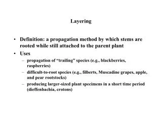
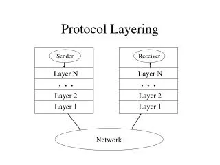
Masking the Overhead of Protocol Layering. CS514: Intermediate Course in Operating Systems. Robbert van Renesse Cornell University Lecture 14 Oct. 12. Layering. Lecture given by Robbert van Renesse First, some background slides from CS514 in Fall 1999

E N D
Masking the Overhead of Protocol Layering CS514: Intermediate Course in Operating Systems • Robbert van Renesse • Cornell University • Lecture 14 Oct. 12
Layering • Lecture given by Robbert van Renesse • First, some background slides from CS514 in Fall 1999 • Then Robbert’s slide set from Thursday October 12
Horus research focal points • Extremely high performance despite modularity of architecture • Consistency in asynchronous systems that tolerate failures • Predictable real-time throughput and failure reaction times • Integration with security solutions • Use formal methods to verify protocols
Lego Building Blocks for Robustness identify a component or subsystem
Lego Building Blocks for Robustness wrapped component Wrap the component at an appropriate interface. Ideally, the underlying code remains unchanged. Wrapper may transform component to confer property add new interfaces monitor or control component in some way
Lego Building Blocks for Robustness wrapped component • Horus wrapper options: • Library interposition layer (bsd sockets, Tk/Tcl, Panda • Pcode (for MPI), Unix system call layer (for virtual fault- • tolerance), explicit Horus library interfaces (HCPI)) • Packet filter in O/S or firewall • Potential wrapper: Object code editor
Potential Wrapper Functions • Virtual fault tolerance • Authentication, data integrity, encryption • Analytic redundancy (behavior checking) • Packet filtering • Service and resource negotiation • Resource use monitoring & management • Type enforcement for access control
Lego Building Blocks for Robustness wrapped component “Secure fault-tolerance” In some cases, more than one wrapper might be needed for the same component, or even the same interface. For example, a data encryption security wrapper might be ``composed’’ with one that does replication for fault-tolerance.
Lego Building Blocks for Robustness wrapped component group of replicas (e.g., for fault tolerance) REPLICATE FORFAULT-TOLERANCE ftol Plug in modules implement communication or protocol. The wrapper hides this structure behind the wrapped interface vsync encrypt
Lego Building Blocks for Robustness Component wrapped for secure fault-tolerance Environment sees group as one entity group semantics (membership, actions, events) defined by stack of modules ftol Horus stacks plug-and-play modules to give design flexibility to developer vsync sign filter encrypt
Horus Common Protocol Interface • Standard used in stackable protocol layers (concealed from application by upper “wrapper” layer). • Generalizes group concepts: • Membership • Events that happen to members • Communication actions • “Layers bind semantics to interfaces”
How a layer works • Layer’s “state” is private, per connection • Layer can add headers to messages • Idea is to run a protocol with respect to peer layers at other group members • Typically 1500-2500 lines of code in C, shorter in ML • Example: signature layer signs outgoing msgs, strips incoming signatures, uses Kerberos to obtain session keys
Extended virtual synchrony • Consistency model used in Horus, reflects Totem/Transis extentions to Isis model • Delivery atomicity w.r.t. group views, partition merge through state transfer • Optimal availability for conflicting operations (c.f. recent theoretical work) • Selectable ordering, user defined stabilization properties, stabilization-based flow control
Horus as an “environment” • Builds stacks at runtime, binds to groups • Offers threaded or event queue interfaces • Standard message handling, header push/pop, synchronization • Memory “streams” for memory management • Fast paths for commonly used stacks • Code in C, C++, ML, Python • Electra presents Horus as Corba “ORB”
Examples of existing layers • Virtually synchronous process group membership and delivery atomicity • Ordering (fifo, causal, total) • Flow control and stability • Error correction • Signatures and encyrption • Real-time vsync layers and protocols
Possible future layers? • Fault-tolerance through replication, Byzantine agreement, behavior checking • Security through intelligent filtering, signatures, encryption, access control • Transactional infrastructure • Group communication protocols • Layers for enforcing performance needs • Layers for monitoring behavior and intervening to enforce restrictions, do software fault-isolation • Load-sharing within replicated servers • Real-time, periodic or synchronized action
Electra over Horus, HOT • Developed by Maffeis, presents Horus as a Corba ORB, full Corba compliance • Vaysburd: Horus Object Tools • Protocol stack appears as class hierarchy • Developing a system definition language (SDL) to extend component-oriented IDL with system-wide property information • Performance impact minimal
Problems With Modularity • Excessive overhead due to headers on packets (each layer defines and pads its own headers, cummulative cost can be high) • High computing costs (must traverse many layers to send each packet)
Horus Protocol Accelerator Cuts Overhead From Modularity • Van Renesse (SIGCOMM paper) • “Compiles” headers for a stack into a single highly compact header • Doesn’t send rarely changing information • Restructures layers to take “post” and “pre” computation off critical path • Uses “packet filter” to completely avoid running stack in many cases • “Beats” a non-layered implementation
Objective • Software Engineering and Performance appear at odds: • layering • high-level language • Horus reports >50 microseconds per layer • You can have good SE and performance! bad performance
Layering is good • Modularity • Flexibility • Easy testing • Stacks together like Lego blocks
Problems with Layering • Crossing layer boundaries results in • interface calls • non-locality of data and instruction • Each layer aligns headers separately • Alignment of individual fields not optimal
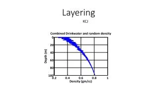
Losing Performance is Easy Round-trip Latency (æS) • Keep headers small • Keep processing minimal Raw U-Net Message size (bytes)
How to Reduce Headers? • Mix fields of layers to optimize alignment. • Agree on values that are always, or almost always the same -- e.g., addresses, data type (one for each layer), etc. -- rather than sending them always. • Piggybacked info often does not need to be included on every message! • Typically, the header is now 16 bytes even for as many as 10 layers (down from about 100 bytes). • Speeds up communication anddemultiplexing.
Reducing Processing • Optimize critical path: • 1) Place layer state updates (particularly buffering) outside of the critical path. • 2) Predict as much of the header of the next message as possible. • 3) Use packet filters to avoid layer processing altogether (e.g., calculating or checking CRCs). • 4) Combine processing of multiple messages.
Canonical Protocol Processing • Each layer can always split its operations on messages and protocol state in two phases: • Preprocessing: • - build or check header, but don’t update layer state. E.g., the seqno may be added to the header or checked, but not incremented. • Postprocessing: • - update protocol state. E.g., the sequence number may now be incremented.
Shortening the Critical Path BEFORE • First do pre-processing for all layers, followed by actual message send/delivery. • Then do all post-processing, updating protocol state. • Combine pre-processing with header field prediction to come to an ILP solution. AFTER
New Uses for Packet Filters BEFORE • Used for checking and generating unpredictable header fields such as checksums or message lengths. • Packet filter code is generated by the layers as they are composed. • Preprocessing = bcmp for delivery, or bcopy for sending, plus running the PF, leading to high locality. AFTER PF
Other techniques • When streaming small messages, pack chunks of them together and deal with them as a single entity. • Avoid allocating memory and garbage collection during preprocessing as much as possible.
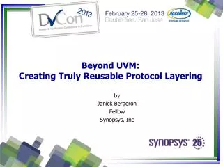
Architecture Application Packer ML Protocol Stack PRESEND PREDELIVER Network
Overview of Performance • Sun Sparc-20, SunOS 4.1.3, U-Net 1.0, Fore SBA-200 140 Mbit/sec ATM, CSL 1.10 compiled, 4 layer protocol (sliding window), 8-byte messages.
Detailed Round-Trip Times SEND() 0 DELIVER() SEND() DELIVER() POSTSENDDONE POSTSENDDONE POSTDELIVER DONE POSTDELIVER DONE 400 400 GARBAGE COLLECTED GARBAGE COLLECTED 700 æS 700
Use of a High-Level Language • We achieve similar performance using O’Caml only. • The code of the system is 9 times smaller than the C version, 10 times faster using the PA techniques, and lots more robust. • O’Caml is a fully capable system language. • Tag-free, real-time garbage collector would make the language ideal for systems.
Conclusions • Layering need not result in overhead • (on the contrary -- improved code development results in better performance).